

Tube sampler capable of realizing under-pressure sampling, isothermal sampling and anti-shear sampling, and sampling method
A sampler and anti-shear technology, applied in the sampling device and other directions, can solve the problems of difficult piston movement, increased workload, complex structure and sealing, and achieve the effect of reducing sampling workload, avoiding shearing effect, and reliable sealing
- Summary
- Abstract
- Description
- Claims
- Application Information
AI Technical Summary
Problems solved by technology
Method used
Image

Examples
Embodiment 1
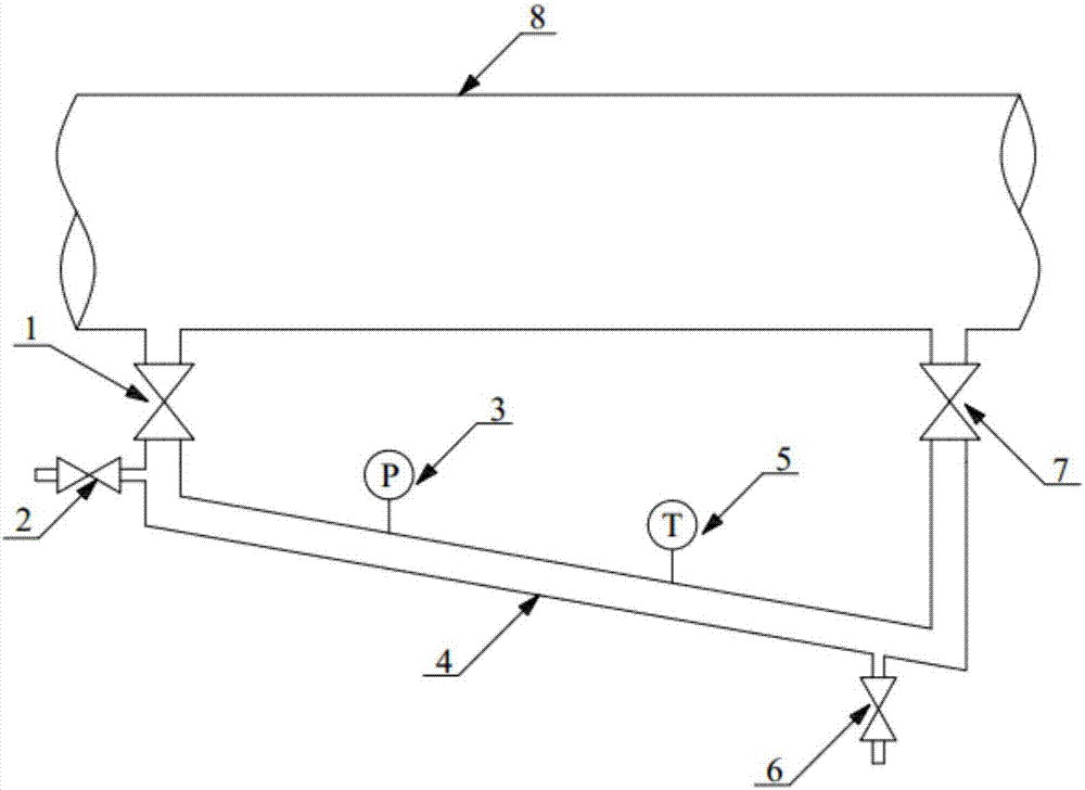
[0036] This embodiment 1 provides a tubular sampler for isothermal anti-shear sampling under pressure, which can directly sample under pressure, isothermal sampling, and anti-shear sampling without affecting the normal transportation process of the crude oil pipeline 8, and No external force is required for sampling, the structure is simple, and the seal is reliable.
[0037] Such as figure 1 As shown, the tubular sampler includes a bypass pipeline 4 inclined relative to the horizontal line, preferably the inlet end of the bypass pipeline 4 is arranged at a position higher than the outlet end; the two ends of the bypass pipeline 4 are respectively connected to the bottom of the crude oil pipeline 8 The connection can be opened and closed, so as to realize the pressure sampling from the crude oil pipeline 8, the bypass pipeline 4 is used to continuously lead out and seal the oil from the crude oil pipeline 8, and use the oil to continuously flow into the bypass pipeline 4 to ac...
Embodiment 2
[0046] Based on the tubular sampler described in Embodiment 1, this Embodiment 2 proposes a sampling method, which is used to directly sample from the crude oil pipeline 8 with isothermal anti-shear under pressure, and will not affect the normal transportation of the crude oil pipeline 8 process, and there is no need to add additional internal and external drive devices, the structure is simple, and the seal is reliable.
[0047] This sampling method includes the following steps:
[0048] S1. Put the tube sampler in the initial state. In the initial state, the inlet control valve 1, the outlet control valve 7, the leakage inlet valve 2 and the sampling valve 6 must all be closed.
[0049] S2. Connect one end of the bypass pipeline 4 of the tubular sampler to the crude oil pipeline 8, and disconnect the other end from the crude oil pipeline 8, introduce the oil in the crude oil pipeline 8 into the bypass pipeline 4 in one direction, and connect the bypass pipe The gas in the r...
PUM
 Abstract
Description
Claims
Application Information