Distribution network fault line selection method based on transient energy difference
A distribution network fault and transient energy technology, applied in the direction of measuring electricity, fault location, measuring electrical variables, etc., can solve the problems of increased workload of distribution network operation and maintenance, increase of distribution network, etc., to improve line selection protection Margin, line selection principle is simple, the effect of high accuracy
- Summary
- Abstract
- Description
- Claims
- Application Information
AI Technical Summary
Problems solved by technology
Method used
Image


Examples
Embodiment 1
[0026] Embodiment 1: A distribution network fault line selection method based on transient energy difference, a distribution network simulation model is built according to the actual operation of the distribution network, and different lines and phase-specific grounding faults are set in the simulation model, and the distribution network is obtained. Each line of the power grid generates a corresponding transient zero-sequence current signal i 0i (t) and bus zero-sequence voltage signal u 0 (t); Select the zero-sequence current i within 5ms after the fault 0i (t) and zero sequence voltage u 0 (t), and then according to the zero-sequence energy function W i (t), to obtain the transient energy W of each line within 5ms after the fault i , and then obtain the average transient energy of the line Using transient energy W i and transient energy mean Construct line selection function Ei fault ,when When , line i is a non-faulty line; when Line i is the faulty line.
[...
Embodiment 2
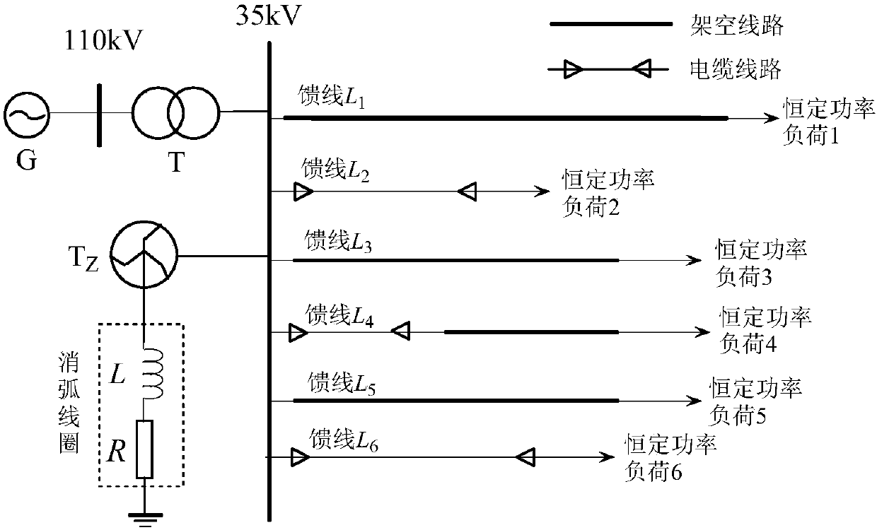
[0045] Embodiment 2: Other parts of this embodiment are the same as Embodiment 1, as figure 1 As shown, the simulation model of 110kV / 35kV distribution network is as follows figure 1 As shown, it has 6 feeders, and the neutral point of the Z-shaped transformer is grounded through the series resistance of the arc suppression coil. Overhead feeder L 1 =18km, L 3 =30km, L 5 = 15km, wire-cable hybrid feeder L 4 =14km, the overhead feeder is 12km, the cable is 2km, and the cable feeder is L 2 = 7km, L 6 = 9 km. G in the power grid is an infinite power source; T is the main transformer, the transformation ratio is 110kV / 35kV, and the connection group is Y N / d11;T Z Is a zigzag transformer; L is the arc suppression coil; R is the damping resistance of the arc suppression coil. The feeder adopts three types of lines: overhead line, overhead line-cable hybrid line and cable line. The load uses a constant power load model. Feeder L 1 A single-phase ground fault occurs in ph...
PUM
 Abstract
Description
Claims
Application Information