Method for calculating magnetic core loss of Boost converter

A technology of magnetic core loss and calculation method, applied in calculation, instrumentation, design optimization/simulation, etc., can solve the problems of multi-material parameters of the model, difficulties in practical application, etc., and achieve the effect of clear physical concept and simple calculation process

A technology of magnetic core loss and calculation method, applied in calculation, instrumentation, design optimization/simulation, etc., can solve the problems of multi-material parameters of the model, difficulties in practical application, etc., and achieve the effect of clear physical concept and simple calculation process

CN107066696AInactive Publication Date: 2017-08-18NANJING UNIV OF POSTS & TELECOMM

Image

  • Method for calculating magnetic core loss of Boost converter
  • Method for calculating magnetic core loss of Boost converter
  • Method for calculating magnetic core loss of Boost converter

Examples


Embodiment Construction

[0029] Below in conjunction with accompanying drawing, technical scheme of the present invention is described in further detail:

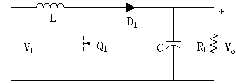
[0030] Such as figure 1 The Boost converter shown works in CCM mode, the inductance is positively excited during the conduction period of Q1, and the flux variation is:

[0031]

[0032] In the formula, V I Represents the input voltage, T represents the temperature, N represents the number of coil turns, A e Represents the cross-sectional area of ​​the magnetic core, and D represents the duty cycle.

[0033] During the cut-off period of Q1, the inductance demagnetizes in reverse, and the amount of flux change is:

[0034]

[0035] In the formula, V O represents the output voltage.

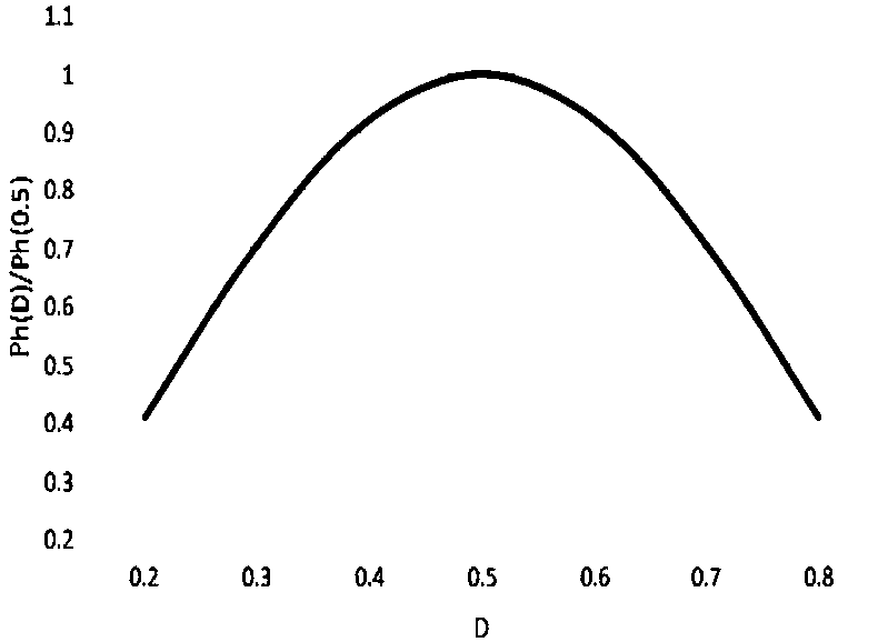
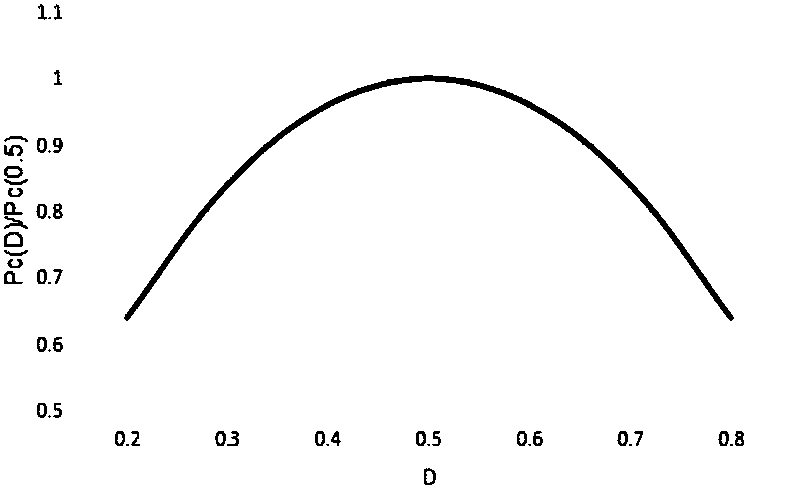
[0036] The eddy current loss in the magnetic core per unit volume of the Boost converter can be expressed as:

[0037]

[0038] In the formula, R e is the core equivalent resistance.

[0039] Eddy current loss under different duty cycle conditions Edd...


PUM


Abstract

The invention discloses a method for calculating magnetic core loss of a Boost converter. Under the condition of determining a change quantity of magnetic flux density when a duty ratio D is equal to 0.5, by analyzing a working principle of a Boost converter circuit, a relational expression among magnetic hysteresis loss, eddy current loss and the duty ratio is established, and a magnetic core loss change law of a magnetic core when the duty ratio of the Boost converter is changed is predicted. The method has the advantages that a physical concept is clear; a calculation process is simple; and the loss of a magnetic core material in an output inductor of the Boost converter under the condition of different duty ratios can be effectively predicted.

Description

technical field [0001] The invention relates to a calculation method for magnetic core loss in a Boost converter, in particular to a calculation method for high-frequency ferrite magnetic cores under different duty cycle conditions. Background technique [0002] Magnetic components are mainly used as transformers and power inductors in high-frequency switching converters. Power magnetic components have a decisive impact on the performance and reliability of switching converters, and unreasonable magnetic component design will cause switching converters to fail. Switching frequency f, magnetic flux density variation B pp , duty cycle D, DC bias H DC , temperature T and other working conditions will have a direct impact on the power loss of magnetic components, which brings significant difficulties to the modeling of core loss. even in B pp Under the same conditions, the core loss will also be affected by the DC bias H DC and the significant effect of excitation waveform ...

Claims


Application Information

Patent Timeline
18 Aug 2017
Publication
CN107066696A
IPC
G06F17/50
CPC
G06F30/20
Inventors
周岩; 陈麒米