Dielectric waveguide filter

A dielectric waveguide and filter technology, applied in the field of dielectric waveguide filters, can solve problems such as insufficient filter strength, and achieve the effects of light weight, high suppression, and effective support structure

Inactive Publication Date: 2017-08-18
SICHUAN TAOGUANG COMM
View PDF6 Cites 2 Cited by
  • Summary
  • Abstract
  • Description
  • Claims
  • Application Information

AI Technical Summary

Problems solved by technology

[0003] Existing dielectric waveguide filters generally use a coupling window with a certain width as the coupling structure of the filter, and the width of the coupling window is generally smaller than the width of a dielectric single cavity; The strength of the filter is not enough; therefore, in order to obtain a better filter waveform response, it is necessary to improve the coupling window structure of the existing dielectric waveguide filter

Method used


Image

  • Dielectric waveguide filter
  • Dielectric waveguide filter
  • Dielectric waveguide filter

Examples


Embodiment 1

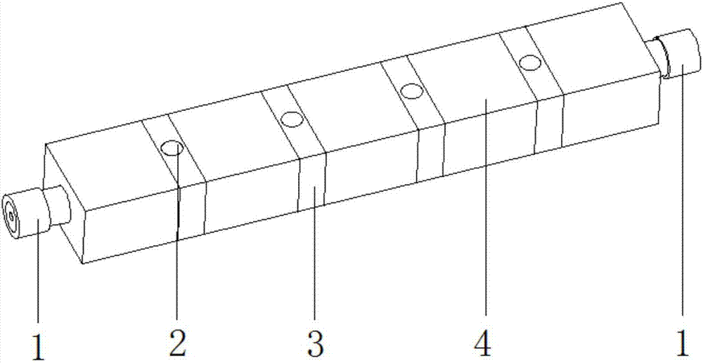
[0037] Such as figure 1 As shown, a dielectric waveguide filter includes a filter body; a radio frequency connector is arranged on the filter body. In this embodiment, the radio frequency connector includes an input radio frequency connector and an output radio frequency connector; the input radio frequency connector and the output radio frequency connector are respectively located at two ends of the filter body.

[0038] The filter body includes a filter dielectric block; the filter dielectric block includes several dielectric single cavities and several coupling windows, and adjacent dielectric single cavities are connected through the coupling windows. Several dielectric single cavities are sequentially connected end to end through coupling windows.

[0039] A through hole is arranged in the middle of the coupling window, and the through hole can be of any shape. In this embodiment, the through hole is a fully rounded rectangular hole with a length L and a width K, and th...

Embodiment 2

[0046] Such as Figure 4 As shown, a dielectric waveguide filter includes a filter body; a radio frequency connector is arranged on the filter body. In this embodiment, the radio frequency connector includes an input radio frequency connector and an output radio frequency connector; the input radio frequency connector and the output radio frequency connector are respectively located at two ends of the filter body.

[0047] The filter body includes a filter dielectric block; the filter dielectric block includes several dielectric single cavities and several coupling windows, and adjacent dielectric single cavities are connected through the coupling windows. Several dielectric single cavities are sequentially connected end to end through the coupling window; the dielectric single cavity can be in any shape, and similarly, the filter body can also be in any shape.

[0048] A through hole is arranged in the middle of the coupling window, and the through hole can be of any shape. ...


PUM


Abstract

The invention provides a dielectric waveguide filter, which solves the problem that an existing dielectric waveguide filter is poor in strength due to structure thereof. The dielectric waveguide filter comprises a filter body. The filter body is provided with a radio-frequency connector and a filter dielectric block. The filter dielectric block comprises a plurality of dielectric single cavities and a plurality of coupling windows. The plurality of dielectric single cavities are connected in a head-to-tail manner in sequence through the coupling windows. Each coupling window is provided with more than one sensitive through hole in the middle. The dielectric waveguide filter can effectively adjust coupling amount of each coupling window to enable the strength of each coupling window to be higher, so that the overall strength of the dielectric waveguide filter is allowed to be higher; the structural strength is more reliable; processing process is allowed to be simpler and more convenient; the dielectric waveguide filter can better meet requirements of low insertion loss, high suppression and high power and the like of the filter, and meanwhile, meets development trend of miniaturization of the filter; and filter signals can be limited within the filter well and are isolated from the external space.

Description

technical field [0001] The invention relates to the field of filters, in particular to a dielectric waveguide filter. Background technique [0002] A filter is a frequency-selective device that allows specific frequency components in a signal to pass, thereby greatly attenuating other frequency components. The waveguide filter is one of the filters used in communication systems, while the traditional waveguide filter is a metal cavity structure with air in the middle, and metal materials as the edges to play the role of electromagnetic shielding and structural support. The traditional waveguide filter has a high Q value, but its volume and weight are large, the production cost is high, and it is not conducive to installation and transportation. With the development of communication systems, filters are required to have the characteristics of low insertion loss, high rejection, high power withstand, low cost, and miniaturization. [0003] Existing dielectric waveguide filte...

Claims


Application Information

Patent Timeline
Patent Type & Authority Applications(China)
IPC IPC(8): H01P1/20H01P1/207
CPCH01P1/2002H01P1/207
Inventor 郭晓宏李松陈萄王国光
Owner SICHUAN TAOGUANG COMM
Why Eureka
Try Eureka