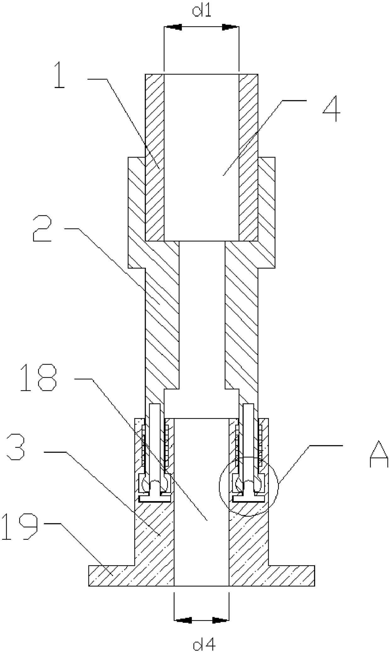
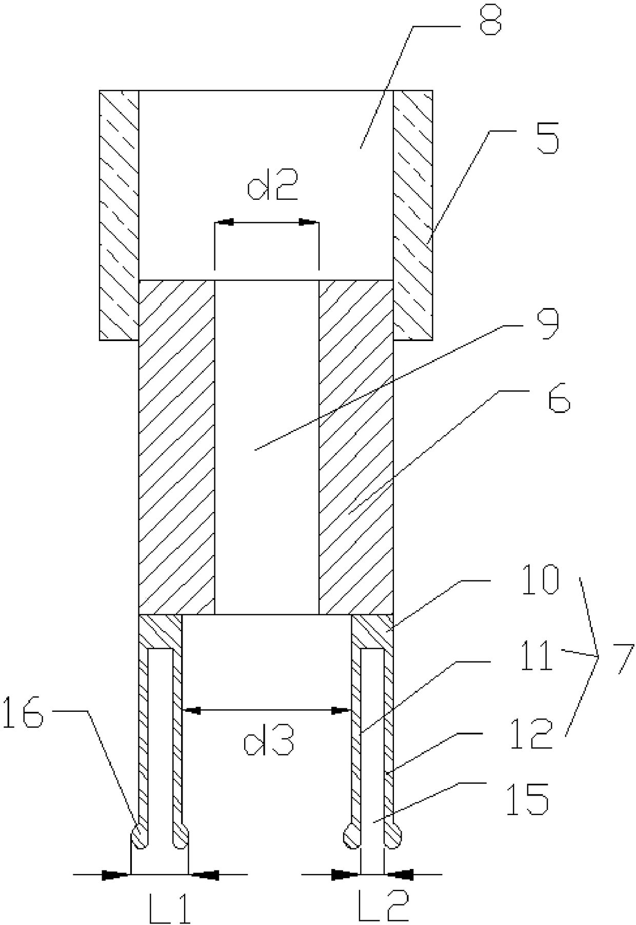
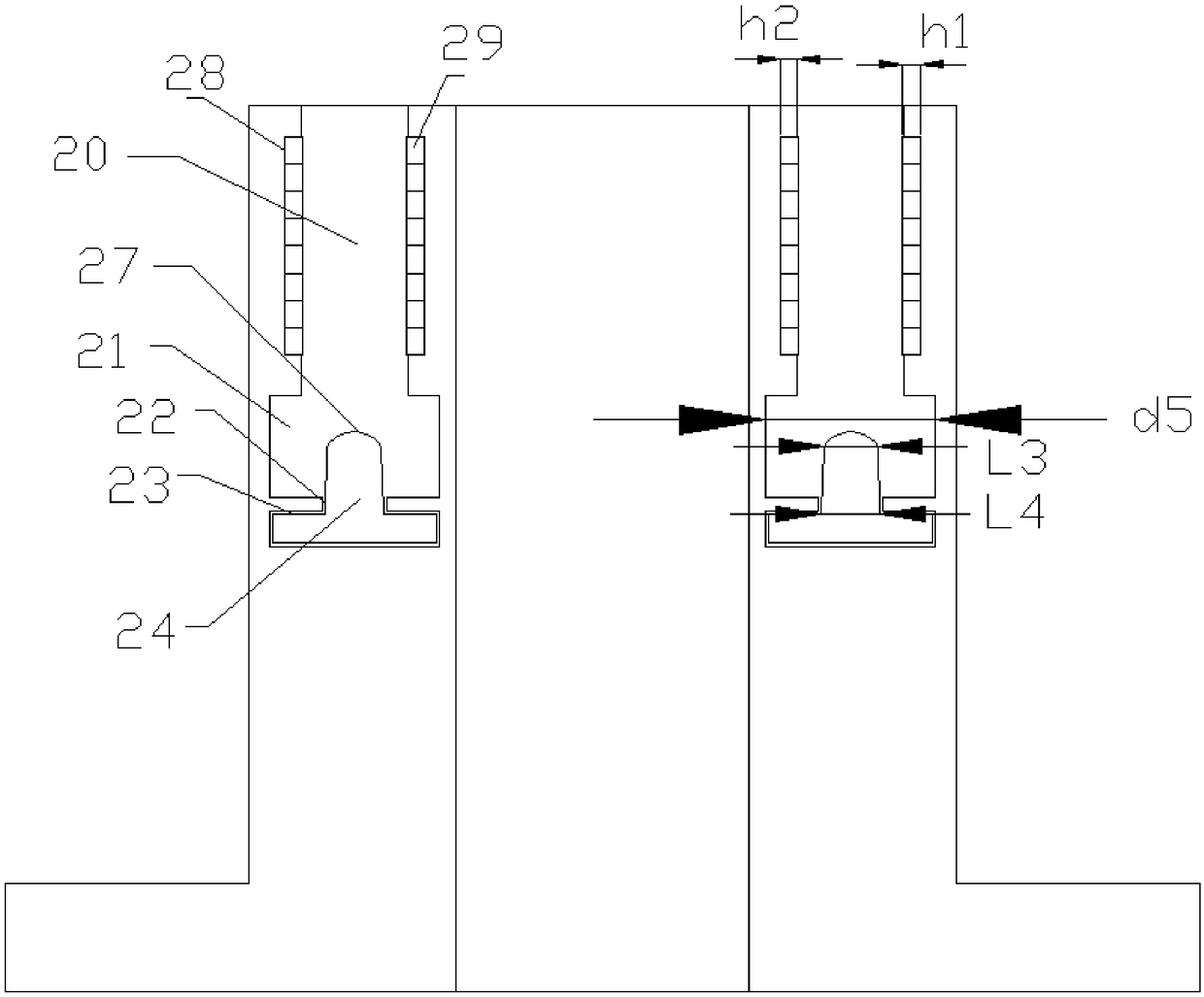
A cable lead-in device for a plug-in cable protection tube
A cable entry device and cable protection tube technology, which is applied to electrical components and other directions, can solve the problems of easy damage to O-rings, damage to the sealing structure, inconvenience in practical use, etc., and achieve the effects of good sealing, good safety and simple structure.
Active Publication Date: 2018-11-02
扬中市众成管路配件有限公司
View PDF6 Cites 0 Cited by
- Summary
- Abstract
- Description
- Claims
- Application Information
AI Technical Summary
Problems solved by technology
However, the O-ring of this cable entry device is installed in the undercut groove, and it is easy to damage the O-ring and then destroy the sealing structure when tightening; the sealing ring is a cylindrical straight wall structure, the compression is not large, and the applicable cable diameter range is relatively large. Narrow; the compression nut uses a chamfer to protect the cable, but it cannot be integrated with the routing steel pipe, which is extremely inconvenient in actual use
Method used
View moreImage
Smart ImageViewing Examples
Examples
Embodiment Construction
[0021] In order to make the technical solution of the present invention clearer, the present invention will be further described below in conjunction with the accompanying drawings. Any solution obtained by equivalent replacement and conventional reasoning of the technical features of the technical solution of the present invention falls within the protection scope of the present invention.
Login to View More PUM
 Abstract
The invention relates to a plug-in type cable protection pipe cable entry device, which comprises a locking mechanism, a threading mechanism and a fixation mechanism. The locking mechanism and the threading mechanism are in screw-thread fit locking and fixation; and the threading mechanism is fixedly arranged to the fixation mechanism in a plug-in manner. The cable entry device is simple in structure, convenient to disassemble and assemble, good in safety and good in sealing performance.
Description
technical field [0001] The invention relates to a cable lead-in device, in particular to a cable lead-in device for a plug-in cable protection tube. Background technique [0002] At present, the structure of the known explosion-proof cable entry device is composed of an entry device body, a compression nut, a rubber sealing ring, an O-ring and a lock nut. First screw the body of the lead-in device into the target housing so that the threads are fully screwed into the compression O-ring or reversely tighten the compression O-ring with the compression nut, then pass the cable through the compression nut, rubber sealing ring, and screw Tighten the compression nut to compress the rubber sealing ring to achieve the purpose of the rubber sealing ring holding the cable tightly. However, the O-ring of this cable entry device is installed in the undercut groove, and it is easy to damage the O-ring and then destroy the sealing structure when tightening; the sealing ring is a cylindri...
Claims
Login to View More Application Information
Patent Timeline
 Patent Type & Authority Patents(China)
IPC IPC(8): H02G3/06
CPCH02G3/0625
Inventor 陆林陆宇峰
Owner 扬中市众成管路配件有限公司
Features
- R&D
- Intellectual Property
- Life Sciences
- Materials
- Tech Scout
- Unparalleled Data Quality
- Higher Quality Content
- 60% Fewer Hallucinations
Learn More Browse by: Latest US Patents, China's latest patents, Technical Efficacy Thesaurus, Application Domain, Technology Topic, Popular Technical Reports.
© 2025 PatSnap. All rights reserved.Legal|Privacy policy|Modern Slavery Act Transparency Statement|Sitemap|About US| Contact US: help@patsnap.com


