Linear oscillation motor for direct drive pump based on selfshield characteristic of Halbach array

An oscillating motor, self-shielding technology, applied in electrical components, electromechanical devices, magnetic circuit shape/style/structure, etc., can solve problems such as the reduction of the effective output force of the motor, the low output flow of the pump system, and the limited power density. The effect of increasing output force, improving dynamic characteristics and high motor utilization rate

Active Publication Date: 2012-07-18
BEIHANG UNIV
View PDF7 Cites 18 Cited by
  • Summary
  • Abstract
  • Description
  • Claims
  • Application Information

AI Technical Summary

Problems solved by technology

[0014] The present invention aims at the problems of low output displacement and low power of the pump system due to the small output displacement of the linear driver used in the current direct-drive hydraulic servo pump, and proposes to apply the linear oscillating motor of the electromagnetic drive mode to the direct-drive hydraulic servo pump to replace the traditional The EHA uses a rotating motor as the linear drive device of the solid-liquid composite steering gear hydraulic servo pump. In addition, the effective output force of the motor is reduced and the power density is reduced due to the large inertial force of the mover when the linear oscillating motor reciprocates at a high frequency. In order to solve the limited problems, a design structure based on the Halbach array permanent magnet hollow mover magnetic circuit is proposed, and a structural design method is proposed to install a resonant spring at the hollow part of the mover to offset the inertial force of the mover

Method used


Image

  • Linear oscillation motor for direct drive pump based on selfshield characteristic of Halbach array
  • Linear oscillation motor for direct drive pump based on selfshield characteristic of Halbach array
  • Linear oscillation motor for direct drive pump based on selfshield characteristic of Halbach array

Examples


Embodiment Construction

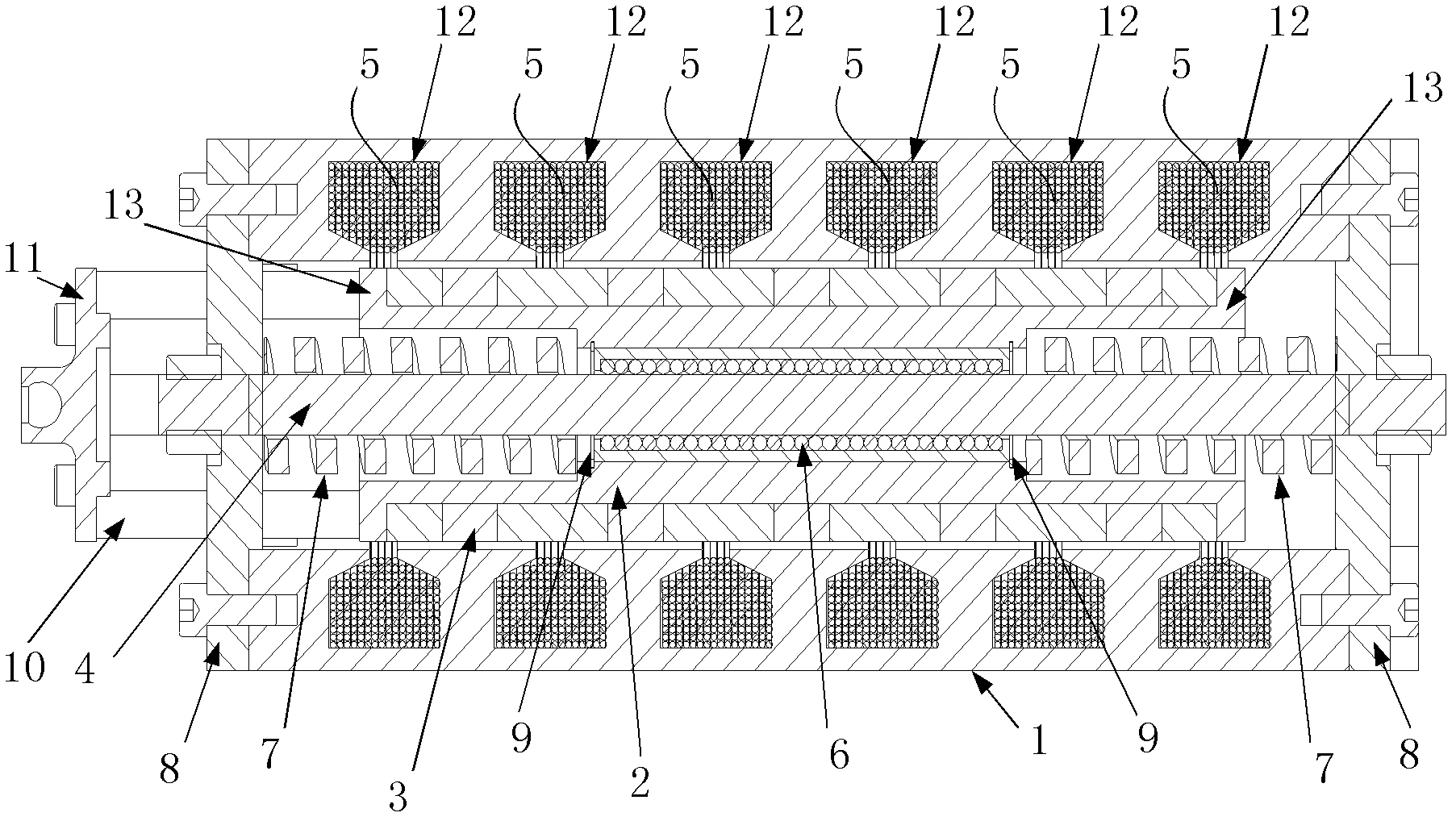
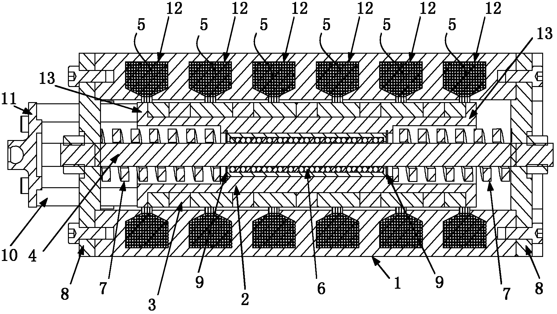
[0030] The present invention will be further described below in conjunction with the accompanying drawings.

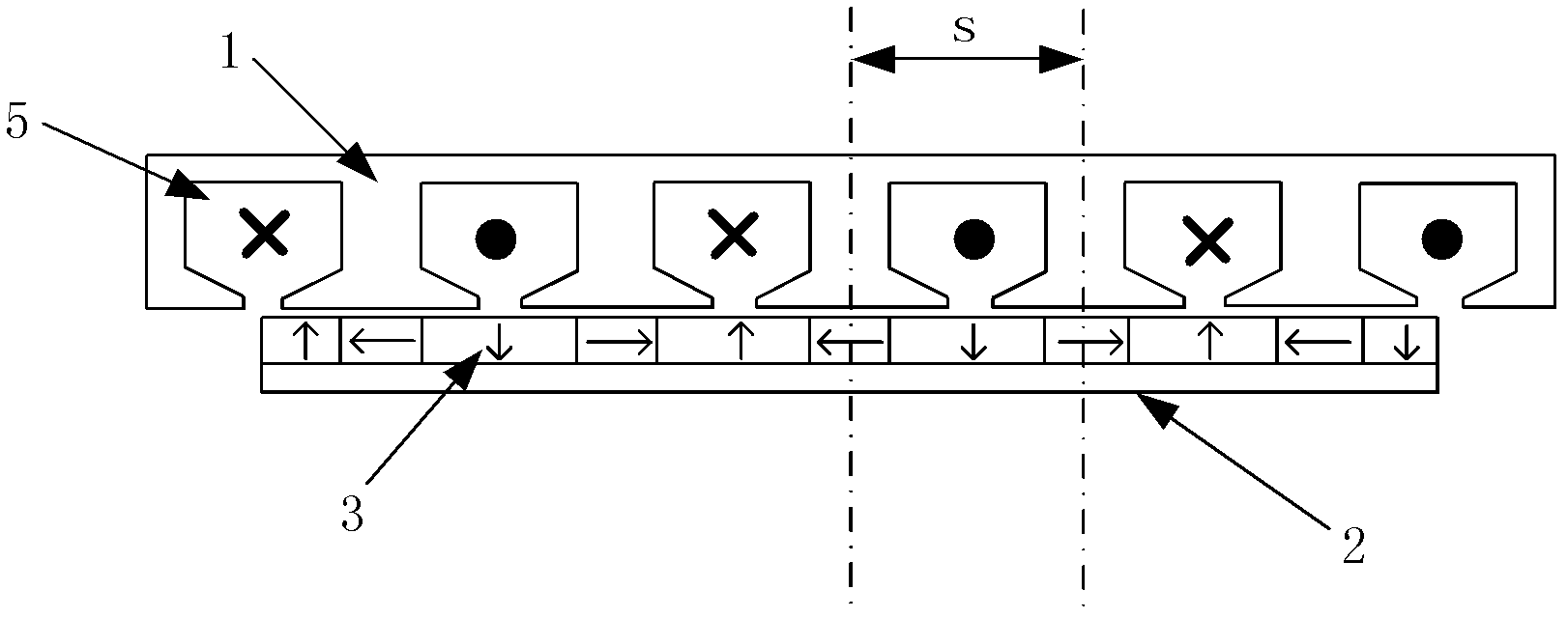
[0031] The linear oscillating motor of the present invention includes an outer layer stator 1 , an inner layer mover 2 , a permanent magnet 3 , a support shaft 4 , a coil winding 5 , a linear bearing 6 , a resonant spring 7 and an end cover 8 .

[0032] Wherein, the outer layer stator 1 is a cylindrical structure. In the present invention, the outer layer stator 1 is designed as a cuboid structure with a cylindrical channel, thereby providing installation and design conditions for the integration of multiple linear oscillating motors in the entire integrated pump. . The inner mover 2 also has a cylindrical structure and is located inside the outer stator 1. Both ends of the inner mover 2 have protruding edges. In the present invention, the outer wall and the outer layer of the inner mover 2 are designed There is an air gap distance of 1mm between the inner walls of th...


PUM


Abstract

The present invention discloses a linear oscillation motor for a direct drive pump based on selfshield characteristic of Halbach array, which comprises the following components: a cylindrical outer stator, an inner rotor, permanent magnets, a supporting shaft, a coil winding, a linear bearing, resonance springs and an end cap. The inner rotor is provided in the outer stator. The inner wall of theouter stator is circumferentially provided with coil winding grooves. The inner rotor can perform oscillation motion in the outer stator. The outer wall of the inner rotor is provided with permanent magnets which are arranged according to a Halbach array arrangement mode. The inner part of the inner rotor is provided with the supporting shaft. Two ends of the supporting shaft are fixed with two ends of the outer stator through end caps. The linear bearing and two resonance springs are sleeved on the supporting shaft. The two resonance springs are provided at two ends of the linear bearing. The resonance springs and the linear bearing are relatively fixed with the inner rotor. After one end of the inner rotor passes through the end cap at the same end, connection with an outer executing mechanism through a spherical hinge joint. The linear oscillation motor has the following advantages: large output force in an axial direction, high utilization rate and compact integral structure.

Description

technical field [0001] The invention relates to a linear oscillating motor, specifically, a linear oscillating motor based on the Halbach array self-shielding characteristic, mainly aimed at directly driving a hydraulic servo pump (direct drive pump) for a solid-liquid integrated actuator. Background technique [0002] At present, the commonly used integrated actuators in the power transmission system: EMA (Electro-mechanical Actuator) with mechanical transmission, EHA (Elector-hydrostatic Actuator) with hydraulic transmission and Integrated electro-hydraulic actuator IAP (Integrated Actuation Package), etc. [0003] Mechanical transmission electromechanical actuator EMA usually includes components such as electric motor, reducer and ball screw. Driven by electric energy, the motor outputs high-speed, low-torque rotary motion, which is converted into low-speed, low-torque rotary motion after the reducer. The rotary motion is finally converted into the linear motion needed t...

Claims


Application Information

Patent Timeline
Patent Type & Authority Applications(China)
IPC IPC(8): H02K33/18H02K33/02H02K1/27
Inventor 焦宗夏梁惠升严亮李洋
Owner BEIHANG UNIV
Why Eureka
Try Eureka