
An amplifier and its realization method
An implementation method and amplifier technology, applied in the field of signal processing, can solve the problems of high cost, design and system cost increase, etc., and achieve the effect of design and system cost reduction
- Summary
- Abstract
- Description
- Claims
- Application Information
AI Technical Summary
Problems solved by technology
Method used
Image

Examples
Embodiment 1
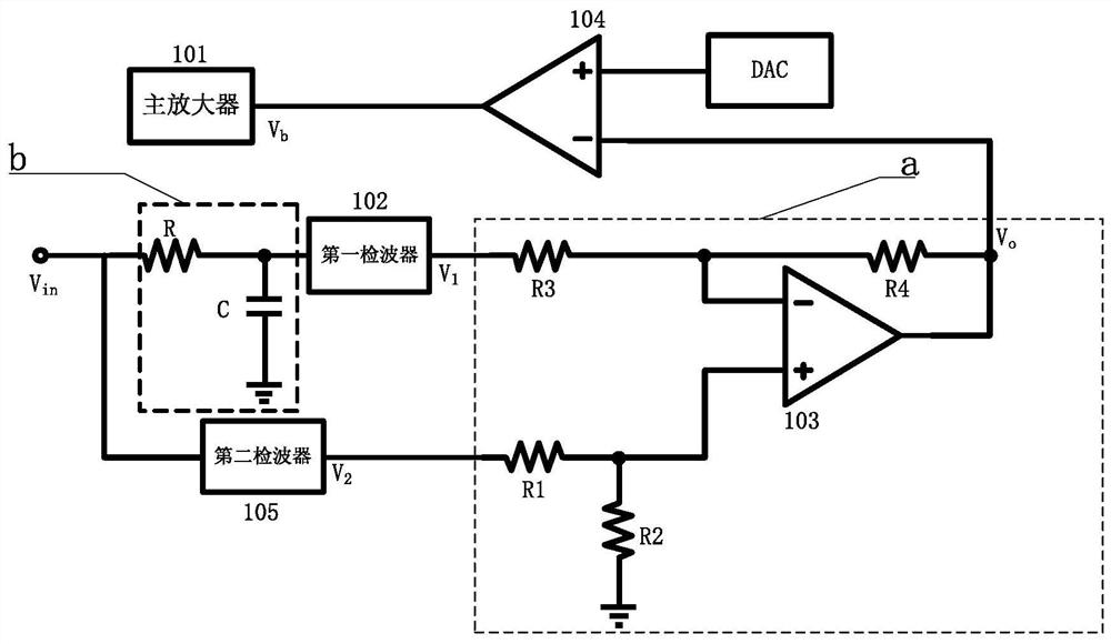
[0026] Such as figure 1 As shown, this embodiment provides an amplifier, including a main amplifier 101, a level comparator 106, a differential amplifier a, a first detector 102, a second detector 105 and a first-order low-pass filter b. Wherein, one end of the first-order low-pass filter b and the second wave detector 105 are respectively connected to the signal input end, and the other end of the first-order low-pass filter b is connected to the first wave detector 102; the first wave detector 102, the second wave detector The output terminals of 105 are respectively connected to the two input terminals of differential amplifier a; the output terminal of differential amplifier a is connected to the inverting input terminal of level comparator 104; the non-inverting input terminal of level comparator 104 is connected to the output terminal of DAC, and the level comparison The output terminal of the device 104 is connected to the main amplifier 101.
[0027] Further, the firs...
Embodiment 2
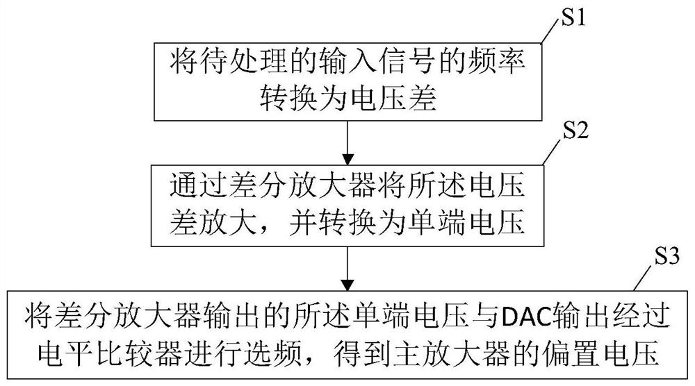
[0040] Such as figure 2 As shown, this embodiment provides a method for implementing an amplifier, including:
[0041] S1) converting the frequency of the input signal to be processed into a voltage difference;
[0042] S2) amplifying the voltage difference through a differential amplifier, and converting it into a single-ended voltage;
[0043] S3) Frequency-select the single-ended voltage output by the differential amplifier and the output of the DAC through a level comparator to obtain a bias voltage of the main amplifier.
Embodiment 3
[0045] This embodiment serves as a preferred implementation of the above-mentioned method embodiment, wherein S1) converts the frequency of the input signal to be processed into a voltage difference, including:
[0046] S11) characterize the frequency of the input signal to be processed by the power difference before and after passing through the first-order low-pass filter, and divide the input signal into two signals with power difference;
[0047] S12) Converting the two signals with a power difference into two voltage signals with a voltage difference through a detector respectively.
[0048] Preferably, wherein S11) characterizes the frequency of the input signal to be processed by the power difference before and after passing through the first-order low-pass filter, and divides the input signal into two signals with power difference, including: dividing the input signal into two , one of which is filtered by a first-order low-pass filter to obtain an attenuated low-power...
PUM
 Abstract
Description
Claims
Application Information