Mounting device for motion sensor and unmanned aerial vehicle
A technology for motion sensors and unmanned aerial vehicles, which is applied to the installation device of motion sensors and the field of unmanned aerial vehicles, can solve the problems of vibration-damping foam detachment, achieve the effect of improving connection reliability and adjusting the vibration-damping effect easily
- Summary
- Abstract
- Description
- Claims
- Application Information
AI Technical Summary
Problems solved by technology
Method used
Image
Examples
Embodiment 1
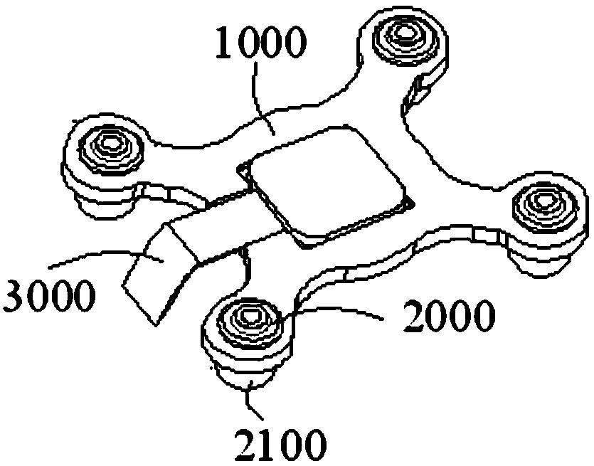
[0030] figure 1 A structural schematic diagram of a motion sensor installation device provided by an embodiment of the present invention; please refer to figure 1 , this embodiment provides a motion sensor installation device, including a mounting frame 1000 and a plurality of vibration-damping mechanisms 2000 . In the illustrated embodiment, the motion sensor is described using an IMU as an example.
[0031] The mounting frame 1000 is used for carrying the motion sensor 3000 . A plurality of vibration damping mechanisms 2000 are connected to the installation frame 1000 and are used for damping the vibration of the installation frame 1000 .
[0032] Wherein, a plurality of damping mechanisms 2000 are arranged at intervals, and each damping mechanism 2000 includes an elastic member 2100 , and the elastic member 2100 abuts against the mounting frame 1000 to damp the mounting frame 1000 .
[0033] Specifically, the mounting frame 1000 can be made of plastic or other low-densit...
Embodiment 2
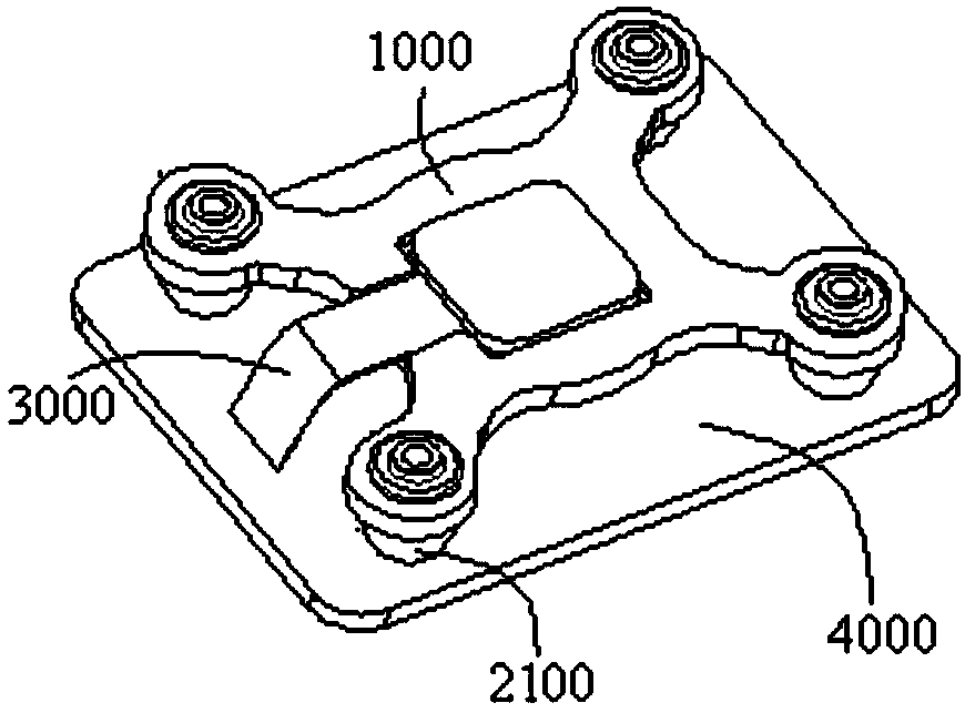
[0039] figure 2 The second structural schematic diagram of the installation device of the motion sensor provided by the embodiment of the present invention; please refer to figure 2 As shown, on the basis of the first embodiment above, further, the elastic member 2100 can be disposed under the installation frame 1000 , and the installation frame 1000 can press the elastic member 2100 to cause the elastic member 2100 to compress and deform.
[0040] In this embodiment, the mounting frame 1000 can be pressed on the carrier frame below the aircraft fuselage 4000 by the elastic member 2100, the elastic member 2100; the vibration transmitted from the aircraft fuselage 4000 to the mounting frame 1000 can be buffered by the compression deformation of the elastic member 2100 , so as to realize the vibration reduction of the installation frame 1000, and further realize the vibration reduction of the motion sensor 3000, which is helpful to improve the measurement accuracy of the motion ...
Embodiment 3
[0044] On the basis of the first embodiment above, further, the elastic member 2100 may also be arranged above the installation frame 1000 , and the installation frame 1000 can pull the elastic member 2100 to cause the elastic member 2100 to be stretched and deformed.
[0045] In this embodiment, the mounting frame 1000 can be suspended under the carrier frame of the aircraft fuselage through the elastic member 2100, and the elastic member 2100 can buffer the vibration transmitted from the aircraft fuselage to the mounting frame 1000 through the tensile deformation of the elastic member 2100, thereby realizing The vibration reduction of the installation frame 1000 , and thus the vibration reduction of the motion sensor 3000 , helps to improve the measurement accuracy of the motion sensor 3000 .
[0046] Among them, terms such as "upper" and "lower" are used to describe the relative positional relationship of each structure in the drawings, which are only for the convenience of ...
PUM
 Abstract
Description
Claims
Application Information
 - R&D
- Intellectual Property
- Life Sciences
- Materials
- Tech Scout
- Unparalleled Data Quality
- Higher Quality Content
- 60% Fewer Hallucinations
Browse by: Latest US Patents, China's latest patents, Technical Efficacy Thesaurus, Application Domain, Technology Topic, Popular Technical Reports.
© 2025 PatSnap. All rights reserved.Legal|Privacy policy|Modern Slavery Act Transparency Statement|Sitemap|About US| Contact US: help@patsnap.com


