Corner connector for rod-shaped profile elements

A corner connector and component technology, applied in furniture connection, connecting member, application and other directions, can solve the problems of complex frame or structure, unable to absorb corner pillars and side cheeks, unable to construct corner connectors, etc., to achieve simple disassembly, Quick and easy reassembly and disassembly, stable frame structure effect

Inactive Publication Date: 2017-08-18
埃克哈德希尔默
View PDF7 Cites 3 Cited by
  • Summary
  • Abstract
  • Description
  • Claims
  • Application Information

AI Technical Summary

Problems solved by technology

Even then, the structures described in the prior art are unable to absorb any appreciable forces acting between the corner struts and the side cheeks, and are therefore only suitable for the application described therein as a bed frame, in which the use of The force applied to the slatted frame, mattress and user acts approximately vertically downward and parallel to the stop surface between the corner post and the side cheeks
Furthermore, it is not possible to construct more complex frames or structures using the corner connectors known from GB 2391802 A because the known corner connectors are only suitable for a maximum of two side cheeks

Method used


Image

  • Corner connector for rod-shaped profile elements
  • Corner connector for rod-shaped profile elements
  • Corner connector for rod-shaped profile elements

Examples


Embodiment Construction

[0054] In the following description, components that perform the same or similar functions are denoted by the same reference numerals even though the specific configurations of the components vary in each embodiment.

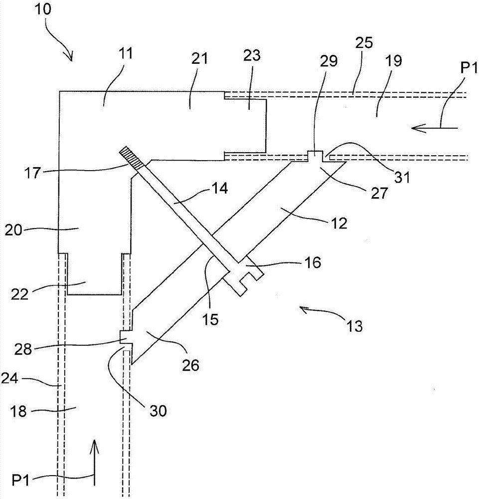
[0055] figure 1 A first exemplary embodiment of a corner connector 10 according to the invention for connecting rod-shaped profile elements is shown. The corner connector 10 comprises a connecting element 11 , a cross bar 12 and a tightening element 13 . In the example shown, the tightening element 13 comprises a hexagon socket head screw 14 inserted through a hole 15 formed in the crossbar 12 and whose screw head 16 rests on the crossbar 12 . The socket head cap screw 14 is screwed into a thread 17 formed in the connection element 11 . In the example shown, two rod-shaped profile elements 18, 19 (in figure 1 ) are connected to each other at an angle of 90° by means of connecting elements 11 . To this end, the connecting element 11 has two arms 20 , 21 which...


PUM


Abstract

The invention relates to a corner connector (10) for rod-shaped profile elements, with a connection element (11) which comprises at least two attachment portions (20, 21) which are oriented substantially perpendicular to each other and which are each designed such that an attachment portion (20, 21) and a front end of the rod-shaped profile elements (18, 19, 39) to be connected engage in each case one inside the other, at least one transverse strut (12) of which the ends (26, 27) are designed such that an end (26, 27) of the transverse strut (12) and a connection portion (30, 31, 48, 49) provided on a lateral surface of the rod-shaped profile elements (18, 19, 39) to be connected in each case engage releasably one inside the other, and a clamping element (13) which clamps the transverse strut (12) releasably against the corner connector. The invention further relates to an assembly system composed of such corner connectors and supporting or holding frames composed of such corner connectors and profile elements.

Description

technical field [0001] The invention relates to a corner connector for a bar-shaped profile system, an assembly system comprising a plurality of different such corner connectors, and a load-bearing or holding frame assembled from profile elements, at least two profiles The elements are connected to each other via corner connectors. Background technique [0002] Such a support or holding frame is described, for example, in the specification of the applicant's German patent DE 197 34 350 C1. Known load bearing or holding frames have an inner frame or an object held around the holding frame and stabilize the entire frame via a tensile connection, so that the profile elements forming the frame and the corner connectors can be configured as simple plug-in connections and can be Fits without further fastening devices. It is a disadvantage of this known frame that the use feasibility of the tightening system arranged in the interior of the frame is limited. In particular, if non...

Claims


Application Information

Patent Timeline
Patent Type & Authority Applications(China)
IPC IPC(8): F16B12/40F16B12/44F16B12/50F16B12/54
CPCF16B12/40F16B12/44F16B12/50F16B12/54F16B2012/443F16B2012/446A47B47/0016A47B81/00A47F5/10
Inventor 埃克哈德·希尔默
Owner 埃克哈德希尔默
Why Eureka
Try Eureka