Clutch disk with a torsional vibration damper

A technology of torsional vibration damper and clutch disc, which is applied in the direction of clutches, friction clutches, mechanical drive clutches, etc. It can solve the problems of joint impact deterioration and achieve the effect of saving components and long-term decoupling

Active Publication Date: 2017-08-18
SCHAEFFLER TECH AG & CO KG
View PDF5 Cites 5 Cited by
  • Summary
  • Abstract
  • Description
  • Claims
  • Application Information

AI Technical Summary

Problems solved by technology

This has the effect of exacerbating the engagement shock to such an extent that in certain applications even with the aid of measures in the spring damper it is no longer possible to achieve a satisfactory acoustic effect.

Method used


Image

  • Clutch disk with a torsional vibration damper
  • Clutch disk with a torsional vibration damper
  • Clutch disk with a torsional vibration damper

Examples


Embodiment Construction

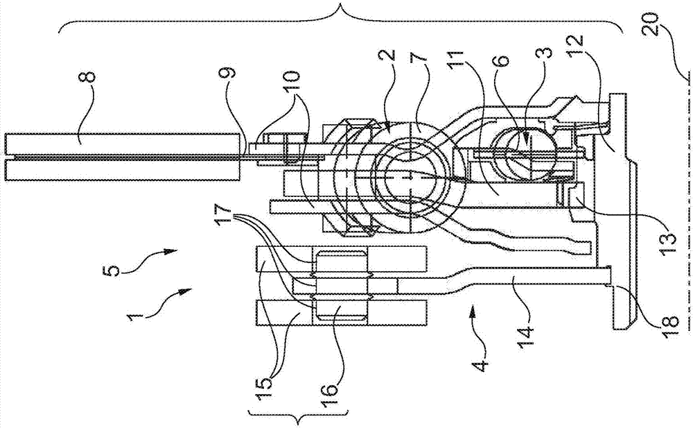
[0046] figure 1A half-sectional view of a clutch disk 1 according to the prior art is shown. The clutch disk 1 shown here is rotatable about an axis of rotation 20 , with which an axial direction or a radial direction or a circumferential direction is also defined. The axial direction is here along the axis of rotation 20 , the radial direction runs in a direction perpendicular to the axis of rotation 20 , and the circumferential direction is correspondingly defined on a trajectory around said axis of rotation 20 . This also applies correspondingly below to the illustrations in the other figures.

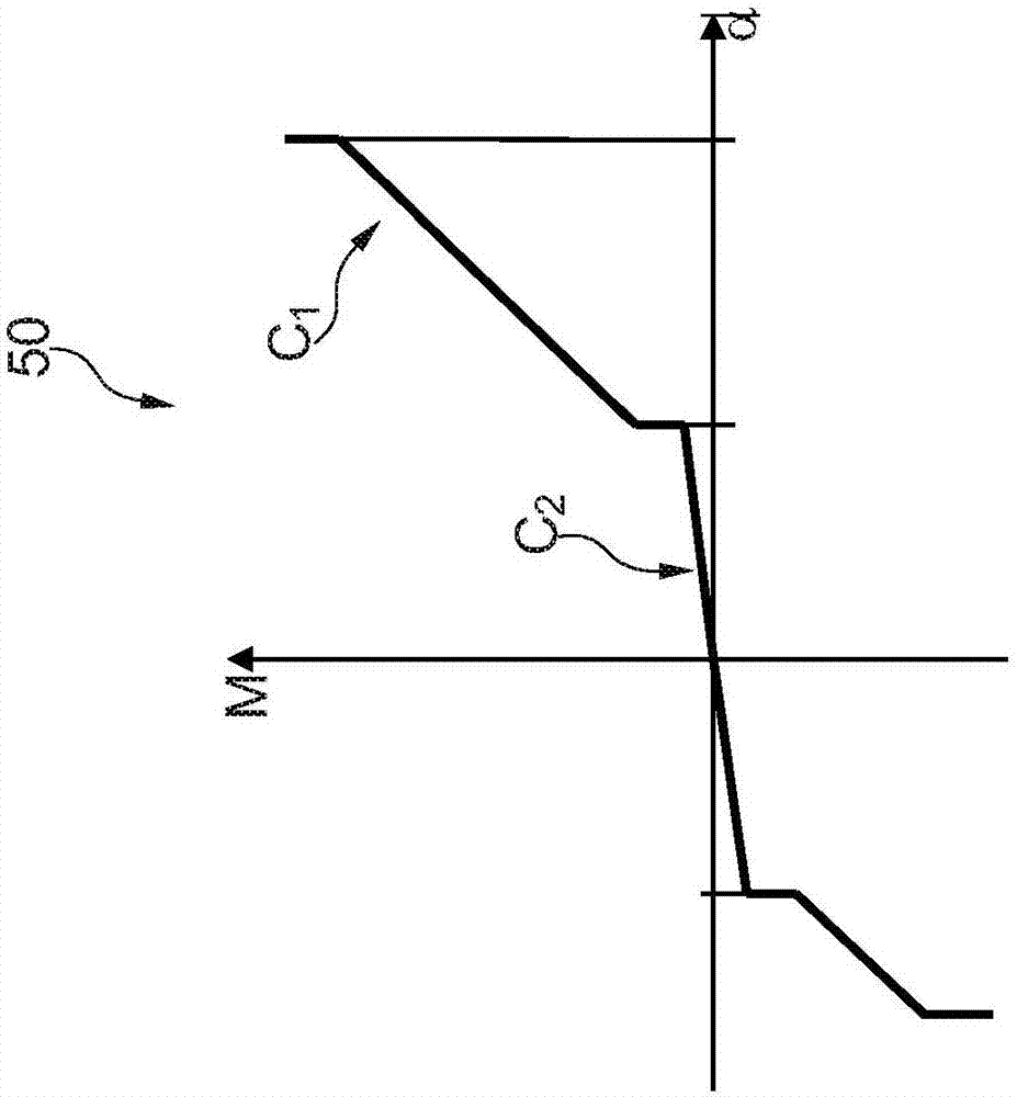
[0047] figure 2 The associated torque characteristic curve 50 of the torsional vibration damper of the clutch disk 1 is shown in a diagram. In this diagram the torque M is plotted as a function of the torsion angle α.

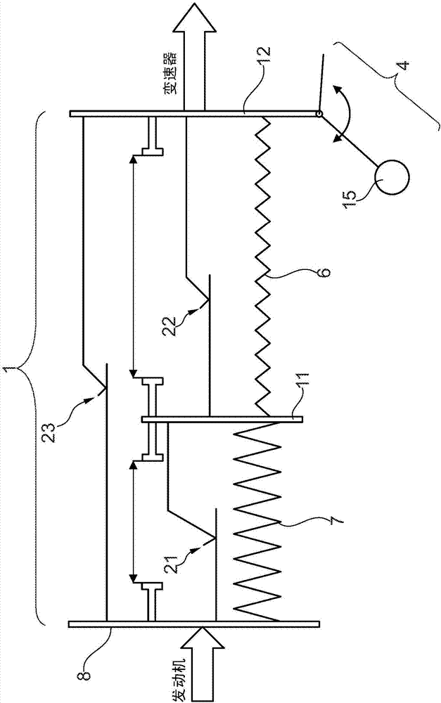
[0048] Here, a damper consisting of two spring dampers 2, 3 connected in series is arranged on the clutch plate 1, namely the first spring damper 2, which is de...


PUM


Abstract

The invention relates to a clutch disk (101) comprising a torsional vibration damper (105) which has two spring dampers (102, 103) connected in series, and comprising a centrifugal pendulum (104) which has a hub (112) and a flange (111) arranged on the hub, and side discs (110) are arranged on both sides of the flange (111), wherein the side discs (110) are connected radially outside to friction linings (108), wherein a first spring damper (102) is arranged as a main damper between the side discs (110) and the flange (111) in a torque-transmitting manner, and a second spring damper (103) is arranged as a pre-damper between the flange (111) and the hub (112) in a torque-transmitting manner, wherein the centrifugal pendulum (104) has at least one flange (114) and centrifugal weights (115) arranged displaceably thereon, wherein the at least one flange (114) of the centrifugal pendulum (104) is hinged to an element of the clutch disk (101) upstream of the second spring damper when viewed in the direction of torque.

Description

technical field [0001] The invention relates to a clutch disc with a torsional vibration damper, in particular for a drive train of a motor vehicle. Background technique [0002] Torsional vibration dampers, also known as torsional vibration dampers, are known in various forms in the prior art. Here too, such a torsional vibration damper with a centrifugal pendulum is known, in which a centrifugal weight is displaceably arranged on the flange, which in the case of torsional vibrations The lower absorbs energy and emits it again with a time delay, so that the torsional vibrations are thereby damped. In this case, the centrifugal weights are displaceably arranged on the flange by means of rolling elements, wherein both the flange and the individual centrifugal weights have guide rails, so that The rolling elements are fitted into the guide rail as bearing elements. [0003] Torsional vibration dampers in clutch disks are also known in which a hub with internal toothing is a...

Claims


Application Information

Patent Timeline
Patent Type & Authority Applications(China)
IPC IPC(8): F16F15/12F16F15/14
CPCF16F15/1238F16F15/145F16D13/644
Inventor A·鲁施S·莱曼
Owner SCHAEFFLER TECH AG & CO KG
Why Eureka
Try Eureka