Coiling machine

A technology of coiling machine and machine body, applied in metal processing equipment, equipment for accumulating materials, manufacturing tools, etc., can solve the problems of synchronous stretching, increased production space occupation, waste of production resources, etc., to achieve the effect of convenient transmission

Active Publication Date: 2017-08-22
浙江飞达环保材料有限公司
View PDF5 Cites 0 Cited by
  • Summary
  • Abstract
  • Description
  • Claims
  • Application Information

AI Technical Summary

Problems solved by technology

[0002] During the processing of copper tubes, the copper tubes coming out of the casting-rolling machine have been stretched for the first time, and then the subsequent drawing is carried out by the combined drawing machine, but due to the stretching rate of the casting-rolling machine and the combined drawing The stretching rate of the drawing machine cannot guarantee the simultaneous stretching of a copper tube; therefore, the copper tube stretched by the casting and rolling machine will be wound up by the coiler, and then passed through the head, and then it will be rolled up. Subsequent stretching by combined drawing machine
[0003] Among them, sometimes customers need to directly obtain the outer diameter model of the copper tube after the first stretching. At this time, most companies will choose to set up a separate straight tube transmission line to connect with the casting and rolling machine, so that the cast and rolled copper tube can be transported out. , which greatly increases the occupation of production space and the waste of production resources

Method used


Image

  • Coiling machine
  • Coiling machine
  • Coiling machine

Examples


Embodiment Construction

[0028] The present invention will be described in further detail below in conjunction with the accompanying drawings.

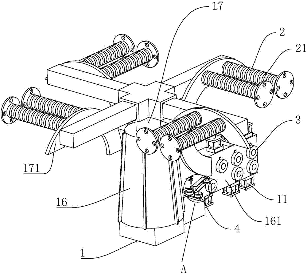
[0029] A coiling machine, refer to figure 1 , this kind of coiling machine includes a body 1, the body 1 includes a base 16 on the lower side, a rotating shaft 17 rotatably connected to the base 16, one end of the rotating shaft 17 penetrates into the inside of the base 16, and the inside of the base 16 is installed with a The reduction motor (not shown) that the rotating shaft 17 rotates; the peripheral side of the rotating shaft 17 away from the end of the base 16 is integrally provided with four mounting seats 171 that are half a C-shaped, and the four mounting seats 171 are on the rotating shaft 17. evenly spaced around the perimeter.

[0030]Mounting base 171 is symmetrically installed with two rewinding reels 2 for rewinding copper tubes, and the peripheral outer wall of rewinding reel 2 is provided with a plurality of annular grooves 21 for copper pip...


PUM


Abstract

The invention discloses a coiling machine comprising a machine body, winding cylinders and guiding rollers. First air cylinders used for driving the multiple guiding rollers to move in the vertical direction are arranged on the machine body. A guiding arm used for abutting against a copper pipe is arranged on the side, close to the guiding rollers, of the machine body. The end, close to the guiding rollers, of the guiding arm is rotatably connected on the machine body. A spring fixed on the machine body is arranged at the end, far from the machine body, of the guiding arm. A cam used for abutting against the guiding arm is rotatably connected on the side, close to the machine body, of the guiding arm. The copper pipe is guided for the first time through a guiding wheel, then the cam rotates to drive the guiding arm to rotate, and when conveyed on the guiding arm, the copper pipe can be conveyed toward the side far from the machine body along the inclined guiding arm; and the copper pipe can be conveyed to the position between a first guiding wheel and a second guiding wheel, final guiding is conducted through the first guiding wheel and the second guiding wheel, and finally the copper pipe conveyed from a casting and rolling machine can be conveniently conveyed out .

Description

technical field [0001] The invention relates to copper pipe manufacturing equipment, in particular to a coiling machine. Background technique [0002] During the processing of copper tubes, the copper tubes coming out of the casting-rolling machine have been stretched for the first time, and then the subsequent drawing is carried out by the combined drawing machine, but due to the stretching rate of the casting-rolling machine and the combined drawing The stretching rate of the drawing machine cannot guarantee the simultaneous stretching of a copper tube; therefore, the copper tube stretched by the casting and rolling machine will be wound up by the coiler, and then passed through the head, and then it will be rolled up. Subsequent stretching is carried out by means of a combined drawing machine. [0003] Among them, sometimes customers need to directly obtain the outer diameter model of the copper tube after the first stretching. At this time, most companies will choose to...

Claims


Application Information

Patent Timeline
Patent Type & Authority Applications(China)
IPC IPC(8): B21C49/00
CPCB21C49/00
Inventor 范汉中廖寒宇江峰杭欢义
Owner 浙江飞达环保材料有限公司
Why Eureka
Try Eureka