Height adjustment device of temporary support and use method of height adjustment device

A height adjustment device and temporary support technology, which is applied in the erection/assembly of bridges, bridges, buildings, etc., can solve the problems of heavy workload and poor adjustment accuracy at the construction site, so as to avoid high-altitude welding operations, improve construction efficiency, The effect of ensuring construction safety

Active Publication Date: 2017-08-22
SHANGHAI CONSTRUCTION GROUP
View PDF5 Cites 0 Cited by
  • Summary
  • Abstract
  • Description
  • Claims
  • Application Information

AI Technical Summary

Problems solved by technology

[0004] Aiming at the problems of the existing height adjustment method of temporary supports, the adjustment accuracy is poor, and the workload of high-altitude operations on the construction site is large, the purpose of the present invention is to provide a height adjustment device for temporary supports and its use method, which combines the elevation of the adjustment rod The fine adjustment of the main adjustment and the adjustment bolts can accurately adjust the elevation of the temporary support, and no high-altitude welding operation is required, which ensures the construction safety and improves the construction efficiency

Method used


Image

  • Height adjustment device of temporary support and use method of height adjustment device
  • Height adjustment device of temporary support and use method of height adjustment device
  • Height adjustment device of temporary support and use method of height adjustment device

Examples


Embodiment Construction

[0027] A height adjustment device for a temporary support and a method of using the same proposed by the present invention will be described in further detail below with reference to the accompanying drawings and specific embodiments. The advantages and features of the present invention will become apparent from the following description and claims. The technical content and features of the present invention will be described in detail below with reference to the enumerated embodiments in conjunction with the accompanying drawings. It should be additionally noted that the accompanying drawings are all in a very simplified form and in inaccurate scales, and are only used to facilitate and clearly assist the purpose of explaining the embodiments of the present invention.

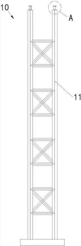
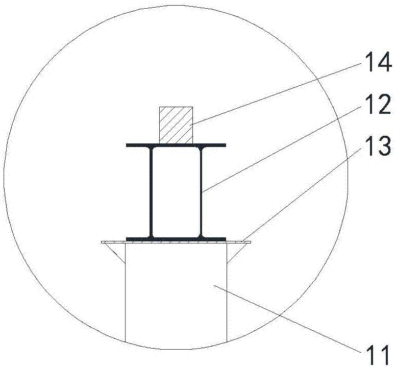
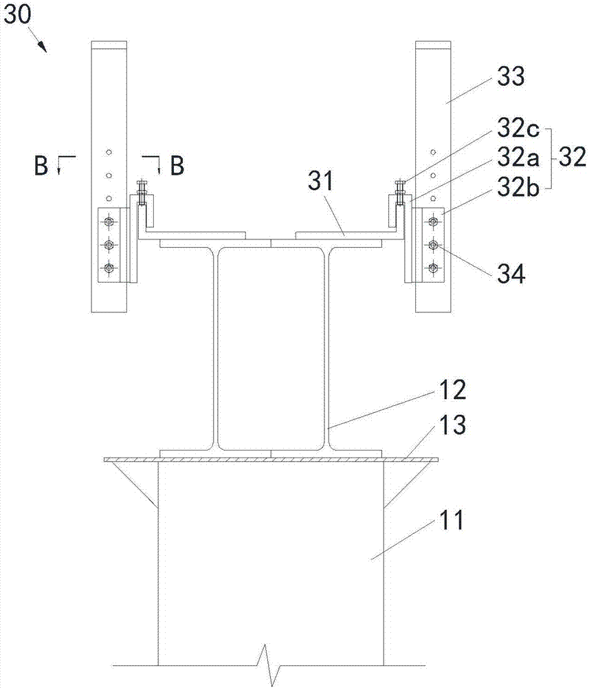
[0028] Please refer to figure 1 and figure 2 The temporary support 10 of this embodiment includes a plurality of uprights 11 , two beams 12 erected on the uprights 11 and arranged side by side, and a steel ...


PUM


Abstract

The invention provides a height adjustment device of a temporary support and a use method of the height adjustment device, relating to the technical field of municipal bridge construction. The height adjustment device comprises a pair of adjusting assemblies which are relatively arranged and connected to a cross beam of the temporary support; each adjusting assembly comprises an L-shaped support, the horizontal part of the L-shaped support is fixedly connected to the cross beam, and the vertical part of the L-shaped support is far from the cross beam; the height adjustment device also comprises hangers and an adjusting rod, wherein each hanger comprises a hanger main body provided with a U-shaped slot and a connecting part as well as an adjusting bolt, each U-shaped slot is buckled at the vertical part of each L-shaped support, the top end of each U-shaped slot is in threaded connection with the adjusting bolt, and the bottom end of the adjusting bolt is butted with the vertical part of each L-shaped support; and the adjusting rod is arranged between a pair of hangers and is in bolted connection with each connecting part. The use method comprises the following steps: assembling the height adjustment device, fixedly connecting the height adjustment device to the cross beam of the temporary support in advance, and hoisting the cross beam so as to be mounted on upright columns; carrying out main adjustment of elevation on the adjusting rod, and fastening the adjusting rod on the hangers; carrying out fine adjustment by virtue of the adjusting bolts until the elevation required for bridge construction is obtained; and erecting a horizontal member of a bridge on the adjusting rod, and dismounting the height adjustment device.

Description

technical field [0001] The invention relates to the technical field of municipal bridge construction, in particular to a height adjustment device for a temporary support and a method for using the same. Background technique [0002] Temporary supports are generally composed of columns, beams and other components. They are widely used in municipal bridge construction and can be used as the main bearing structure for cast-in-place beam and cover beam construction. [0003] Due to the change of the longitudinal slope of the bridge, the erection heights of the temporary supports during the construction are inconsistent, and the erection height of the temporary supports is limited by the specifications of the columns and beams, so it is difficult to erect them to the required elevation at one time. like figure 1 and figure 2 As shown in the figure, at present, the adjustment method of the erection height of the temporary support is as follows: when erecting the temporary suppo...

Claims


Application Information

Patent Timeline
Patent Type & Authority Applications(China)
IPC IPC(8): E01D21/00
CPCE01D21/00
Inventor 苏昱晟李鑫奎
Owner SHANGHAI CONSTRUCTION GROUP
Why Eureka
Try Eureka