
Self-aligning swivel for mounting doors

A rotating device and self-aligning technology, which is applied in door/window fittings, buildings, hinges, etc., can solve problems such as product wear, large door gaps, and installation difficulties, and achieve long service life, reduce wear, and adjust convenient effect

Active Publication Date: 2019-02-22
XUCHANG ZHENGTE GATING TECH
View PDF7 Cites 0 Cited by
  • Summary
  • Abstract
  • Description
  • Claims
  • Application Information

AI Technical Summary

Problems solved by technology

[0002] The connection between the existing traditional door frame and the door body is a hinge (hinge) connection. This method has a simple structure, and it is difficult to achieve the parallelism between the door body and the door frame during installation, and it cannot be debugged during installation. Difficult, if there is a dislocation of installation, the support shaft will be unevenly stressed, forming a certain degree of shaft wear, resulting in more and more force required to open and close the door, serious product wear, and greatly reduced service life. Affected by the weight of the door body
[0003] With the development of technology, the connection method between the door frame and the door body with hidden rotating structure has appeared on the market, which greatly improves the service life and aesthetics. Misalignment will increase the resistance, make the shaft wear seriously, and cause the door gap to become larger and not close tightly; in addition, the existing hidden rotating structure connectors can only adapt to the level ground. If the ground is not smooth, the door body will It is difficult to achieve a consistent gap with the upper and lower spacing between the door frame

Method used


Image

  • Self-aligning swivel for mounting doors

Examples


Embodiment 1

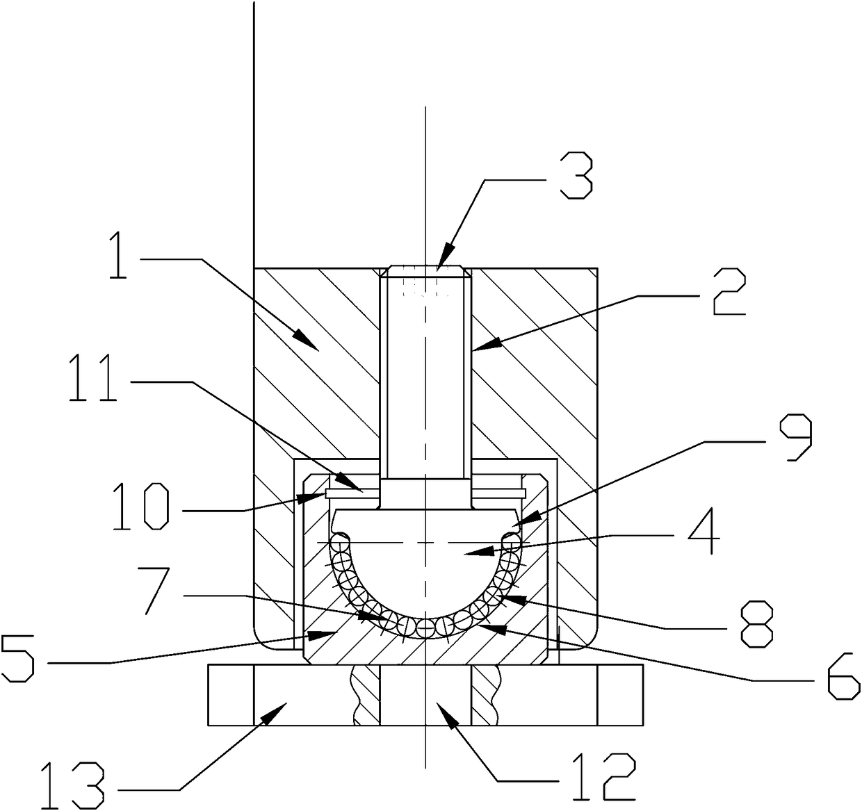
[0015] Embodiment 1: A self-aligning rotating device for installing a door, such as figure 1 As shown, it includes a housing 1 that is fixedly connected with the door body. The upper end of the housing 1 is provided with a ball rod 2 that is threaded. The top of the ball rod 2 passes through the upper end of the housing 1 and is located at the Top surface, the top surface of the club 2 is provided with a concave keyway 3, the keyway 3 is a "one" shape, a "ten" shape or an inner hexagon, by using the keyway 3 matching The screwdriver can tighten the club 2 and adjust the height of the club 2 in the housing 1, thereby fine-tuning the height between the bottom of the door body and the ground to prevent the direct contact between the bottom of the door body and the ground to generate a large frictional force. It is not convenient to open and close the door body. The lower end of the club 2 is provided with a semicircular sphere 4, the sphere 4 and the club 2 are of an integrated ...


PUM


Abstract

The invention relates to the field of connecting devices of door body installation, in particular to a self-aligning rotation device used for installing a door. The self-aligning rotation device comprises a shell fixedly connected with a door body. A ball rod connected in a threaded manner is arranged at the upper end of the interior of the shell. The lower end of the ball rod is provided with a semicircular ball body, and a ball seat is arranged at the lower end of the ball body. The upper end of the ball seat is provided with a groove matched with the ball body, and a ball layer rotating in cooperation with the ball body is arranged in the groove. A cavity is formed between the upper end of the ball seat and the shell, and a pillar is arranged at the lower end of the ball seat. The lower end of the ball seat is provided with a fixing plate fixedly connected with a door frame, and the ball seat and the fixing plate are fixedly connected through the pillar. The self-aligning rotation device is large in bearing force, flexible in rotation, capable of achieving even stress of a door spindle, small in abrasion, capable of adapting to uneven grounds and high in practicability, and the service life is prolonged.

Description

technical field [0001] The invention relates to the field of connecting devices for door body installation, in particular to a centering device for door body installation. Background technique [0002] The connection between the existing traditional door frame and the door body is a hinge (hinge) connection. This method has a simple structure, and it is difficult to achieve the parallelism between the door body and the door frame during installation, and it cannot be debugged during installation. Difficult, if there is a dislocation of installation, the support shaft will be unevenly stressed, forming a certain degree of shaft wear, resulting in more and more force required to open and close the door, serious product wear, and greatly reduced service life. It is greatly affected by the weight of the door body. [0003] With the development of technology, the connection method between the door frame and the door body with hidden rotating structure has appeared on the market,...

Claims


Application Information

Patent Timeline
Patent Type & Authority Patents(China)
IPC IPC(8): E05D7/08E05D11/04
CPCE05D7/08E05D11/04
Inventor 赵泳淇李永建薛玉霞
Owner XUCHANG ZHENGTE GATING TECH
Learn More