Cold reserving part equipped evaporator

a technology of evaporator and evaporator body, which is applied in the field of evaporator, can solve the problems of increasing energy consumption, inconvenience for drivers, and long time for supplying a chilly wind

Active Publication Date: 2009-05-14
HANON SYST
View PDF19 Cites 35 Cited by
  • Summary
  • Abstract
  • Description
  • Claims
  • Application Information

AI Technical Summary

Problems solved by technology

Therefore, there is a problem that a driver may feel inconvenience.
Therefore, there are other problems that it takes long time for supplying a chilly wind and energy consumption is increased.
However, in the thermal energy reserving heat exchanger as shown in FIG. 1, since the dual structural tube 191 is formed by coupling a plurality of plate materials, coupling defects are occurred with increasing frequency and it is difficult to fabricate the tube.
Furthermore, it is difficult to find a portion where the coupling defects are occurred.
However, since the air passing through the outside of the dual structural tube is contacted with the thermal energy reserving material chamber, there is other problem that a rate of heat transfer of the heat exchanging medium is lowered.

Method used


Image

  • Cold reserving part equipped evaporator
  • Cold reserving part equipped evaporator
  • Cold reserving part equipped evaporator

Examples


Embodiment Construction

[0031]

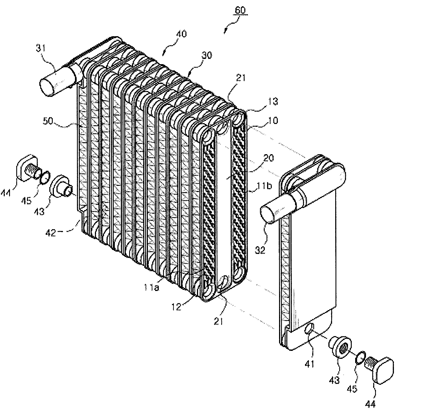
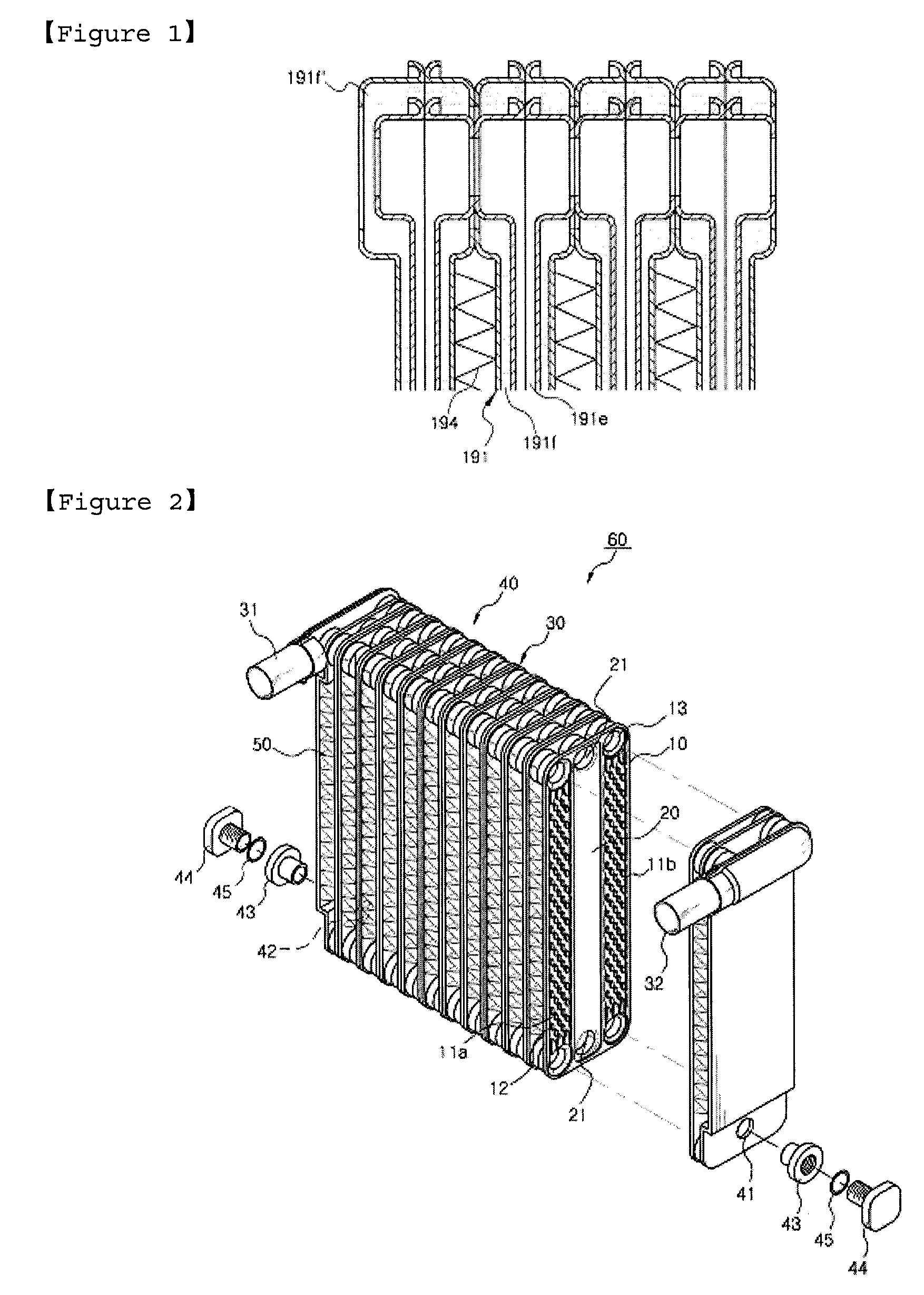
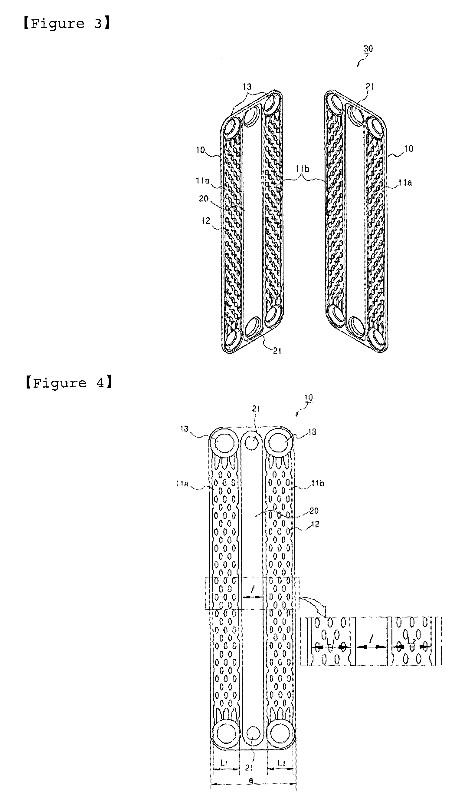
10:plate11a, 11b:refrigerant passage12:bead13:refrigerant flowing cup20:cold reserving part21:hole22:protrusion30:tube31:inlet pipe32:outlet pipe33:communicating portion40:tank41:cold reserving material charging portion42:air discharging portion43:cap44:stopple44:sealing member50:fin60:evaporatorl:width of cold reserving parta:width of plateL1, L2:width of refrigerant passage

Best Mode

[0032]Hereinafter, the embodiments of the present invention will be described in detail with reference to accompanying drawings.

[0033]FIG. 2 is a perspective view of a four-tank type evaporator equipped with a cold reserving part according to the present invention. In the four-tank type evaporator equipped with the cold reserving part 20 according to the present invention, as shown in FIG. 2, a plurality of tubes 30, in which a pair of plates 10 forming independent refrigerant passages 11a and 11b are respectively coupled to both sides thereof, are laminated in a row, and a tank 40 communicated wi...


PUM


Abstract

The present invention provides an evaporator in which a plurality of tubes (30), in which a pair of plates (10) forming independent refrigerant passages (11a) and lib are respectively coupled to both sides thereof, are laminated in a row, and a tank (40) communicated with the tube (30) is formed at an upper or lower side of the tube (30), and the tank (40) is provided with an inlet pipe (31) and an outlet pipe (32), and a plurality of fins (50) are formed between the tubes (30), characterized in that a cold reserving part (20) for storing a cold reserving material is formed between the refrigerant passages (11a) and lib of the tube (30), and integrally formed with the plate (10).

Description

TECHNICAL FIELD[0001]The present invention relates to an evaporator, and more particularly, to a cold reserving part equipped evaporator in which the cold serving part is disposed between refrigerant passages formed of tubes so as to increase the cooling performance and thus to save energy.BACKGROUND ART[0002]In the automobile industry, research studies are carried out to improve mileage according to a growing global interest in the environment and energy, and other studies of downsizing, high-functioning and reducing a weight are also carried out to satisfy various consumers' demands. In particular, various research and developments of a hybrid vehicle using engine power and electric energy are being increased.[0003]The hybrid vehicle mainly selects an idle stop / go system in which an engine thereof is automatically stopped when the vehicle is stopped during waiting the signal and then restarted by operating a transmission. However, an air conditioner of the hybrid vehicle is operat...

Claims


Application Information

Patent Timeline
Patent Type & Authority Applications(United States)
IPC IPC(8): F28F9/02F25B39/02
CPCF28D1/0333F28D1/0341Y02E60/145F28D2021/0085F28D20/02B60H1/005Y02E60/14B60H1/32F25B39/02F28F1/00
Inventor LIM, HONG-YOUNGKEON, DAE BOKPARK, TAE YOUNG
Owner HANON SYST
Why Eureka
Try Eureka