Oilway structure

A technology of oil circuit and structure, applied in the direction of fluid transmission, belt/chain/gear, mechanical equipment, etc.

Active Publication Date: 2017-08-22
JATCO LTD
View PDF7 Cites 1 Cited by
  • Summary
  • Abstract
  • Description
  • Claims
  • Application Information

AI Technical Summary

Problems solved by technology

[0015] However, in order to change the position of the oil passage without changing the po...

Method used


Image

  • Oilway structure
  • Oilway structure
  • Oilway structure

Examples


Embodiment Construction

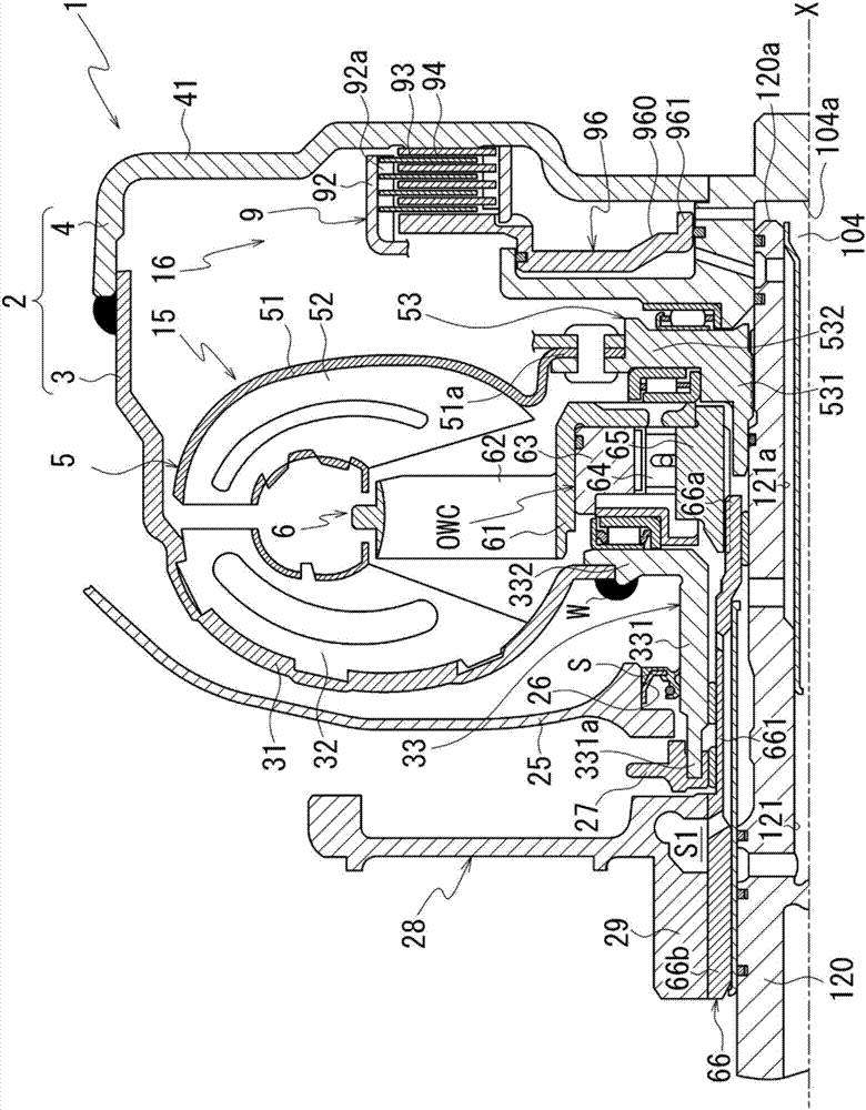
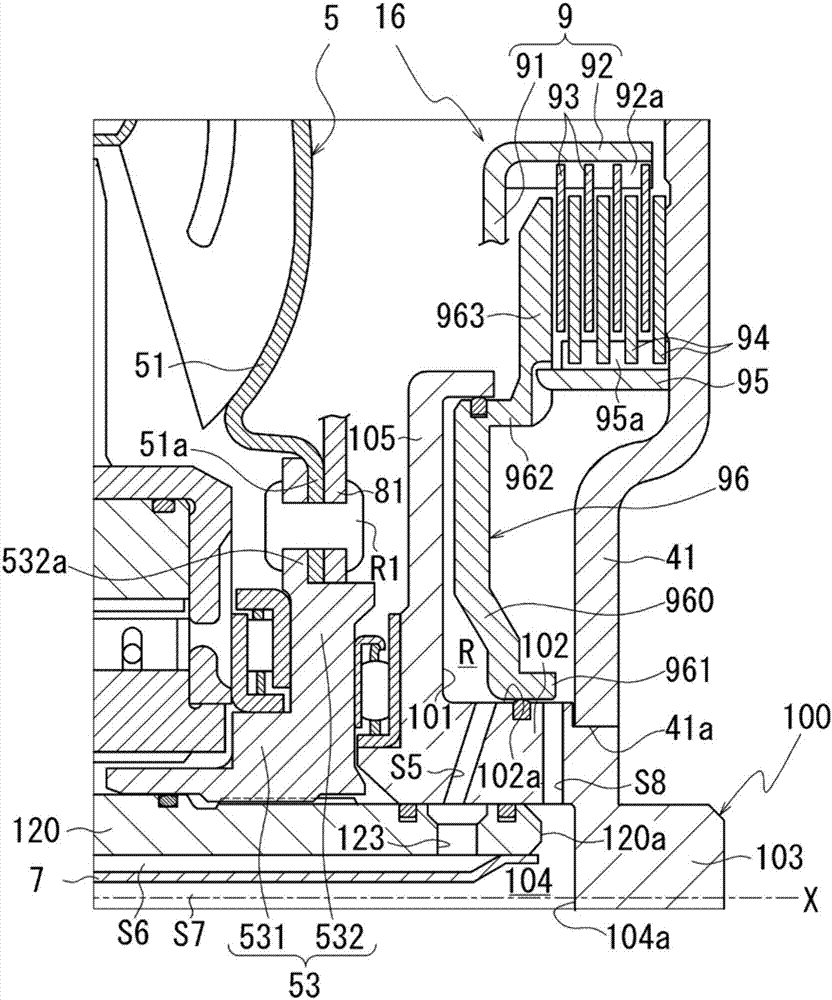
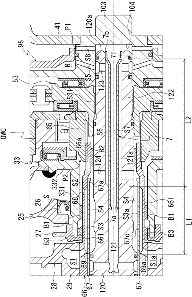
[0090] Hereinafter, an embodiment of the present invention will be described by taking a case where the oil passage structure of the present invention is applied to the oil passage structure of the torque converter 1 as an example. figure 1 It is a diagram explaining the oil passage structure in the torque converter 1 . figure 2 It is an enlarged view of the vicinity of the lockup mechanism portion 16 of the torque converter 1 . image 3 It is an enlarged view around the rotation axis X of the torque converter 1 .

[0091] Such as figure 1 As shown, a torque converter 1 includes a fluid transmission unit 15 and a lockup mechanism unit 16 in a torque converter case 2 composed of a pump impeller 3 and a torque converter cover 4 .

[0092] In the fluid transmission part 15 , the pump impeller 3 and the turbine wheel 5 are provided so as to be relatively rotatable on a common rotation axis X, and the stator 6 is located between the pump impeller 3 and the turbine wheel 5 .

[...


PUM


Abstract

Provided is an oilway structure which can improve setting freedom degree of an oil pressure path. The oilway structure is characterized in that the oilway structure comprises a stator shaft (66), the outer periphery of the stator shaft (66) is provided with a bush (B1), an oilway (S1), and an oilway (S2), the inner periphery of the stator shaft (66) is provided with a sleeve (67), and an oilway (S3) is between the sleeve (67) and the stator shaft (66). The inner periphery of the sleeve (67) is provided with an oilway (S4) separated from the oilway (S3). The oilway (S1) is connected with the oilway (S2) through the oilway (S3). When the oilway is observed from the radial direction of the stator shaft (66), the oilway (S3) and the bush (B1) are overlapped.

Description

technical field [0001] The invention relates to an oil passage structure. Background technique [0002] For example, a hydraulic torque converter with a lock-up clutch has a fluid transmission part formed by a pump impeller, a turbine, and a stator in a torque converter housing composed of a pump impeller and a torque converter cover. A piston constituting a lock-up clutch is provided between the torque converter cover and the torque converter cover. [0003] The lock-up clutch switches between a locked state where the piston is pressed against the torque converter cover and an unlocked state where the piston is not pressed against the torque converter cover by controlling the pressure difference between the supply pressure and the release pressure in the torque converter case , the oil pressure path connected with the torque converter is usually two systems (for example, Patent Document 1). [0004] On the other hand, as another method of the lock-up clutch, there is a me...

Claims


Application Information

Patent Timeline
IPC IPC(8): F16H41/30F16H45/02
CPCF16H41/30F16H45/02F16H2045/0215
Inventor 山下胜则汤川洋久
Owner JATCO LTD
Why Eureka
Try Eureka