Injection molding machine and the molding method thereof

An injection molding machine and molding method technology, applied in the field of injection molding machines, can solve the problems of not considering important factors of the characteristics of the clamping device, not considering the shape elements of the mold gap, and not mentioning the shape elements of the mold gap, so as to achieve molding conditions. simplification and setting simplification, shortening of molding cycle time, and simplification of quality management

Active Publication Date: 2017-10-20
NISSEI PLASTIC IND CO LTD
View PDF5 Cites 2 Cited by
  • Summary
  • Abstract
  • Description
  • Claims
  • Application Information

AI Technical Summary

Problems solved by technology

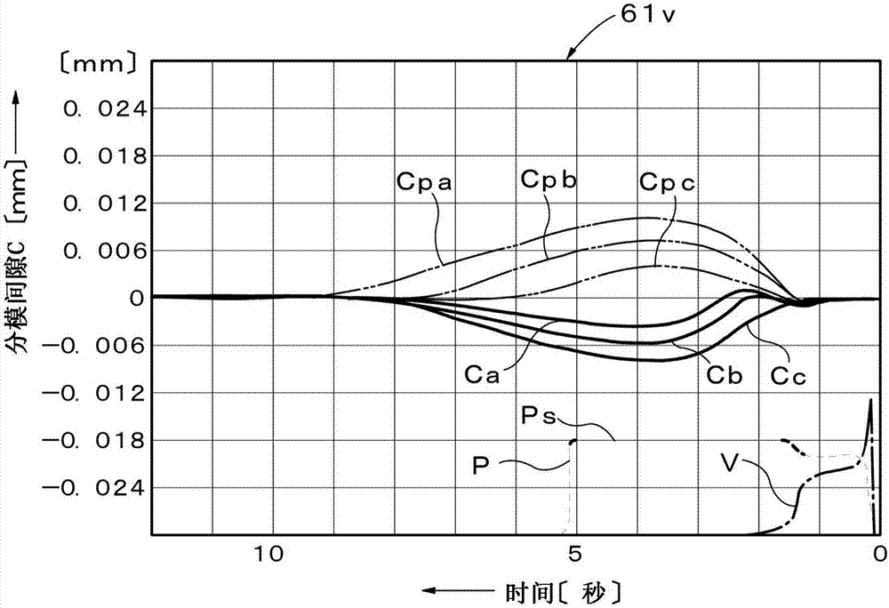
[0007] However, since this molding method focuses on the distance between the mold gaps, the original purpose of ensuring high quality and uniformity of the molded product can be achieved by selecting (setting) the above-mentioned distance, and Realize the simplification and setting of molding conditions, and then realize the simplification of quality control and shortening of molding cycle time, but there is no mention of the shape factor of the mold gap
In addition, as a means for obtaining the mold gap, the structural characteristics of the mold clamping device are utilized, but important factors other than this are not mentioned.
[0008] Thus, in the molding method of the above-mentioned conventional injection molding machine, the shape element of the mold gap is not considered, and as means for obtaining the mold gap, important factors other than the structural characteristics of the mold clamping device are not considered. Therefore, there is room for further improvement from the viewpoint of further optimizing this molding method

Method used


Image

  • Injection molding machine and the molding method thereof
  • Injection molding machine and the molding method thereof
  • Injection molding machine and the molding method thereof

Examples


Embodiment Construction

[0037] Next, preferred embodiments of the present invention will be listed and described in detail based on the drawings. In addition, the drawings do not limit the present invention, but are for facilitating understanding of the present invention. In addition, in order to avoid ambiguity of the invention with respect to a well-known part, detailed description is abbreviate|omitted.

[0038] First, refer to Figure 9 , the overall main structure of the injection molding machine M of this embodiment will be described.

[0039] exist Figure 9 Among them, M is an injection molding machine, which is equipped with an injection device Mi and a mold clamping device Mc. Injection molding device Mi has a heating cylinder 21 having an injection nozzle 21n at the front end and a funnel 21h at the rear. A screw 22 is inserted through the heating cylinder 21 and a Screw drive part 23. The screw driving unit 23 includes an injection cylinder (hydraulic cylinder) 24 having a built-in s...


PUM


Abstract

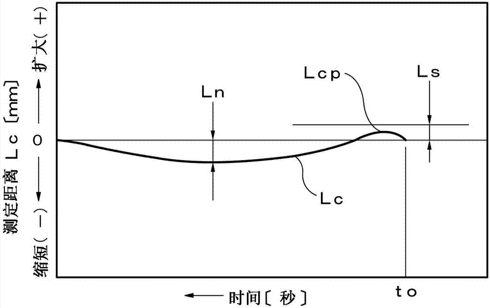
A specific mold status Ac is caused in advance in which the interval of an inner portion Xi in the parting plane direction of a parting gap C between a fixed mold 2c and a movable mold 2m during the injection filling is larger than the interval of an outer edge portion Xo and the interval of the outer edge portion Xo is equal to or lower than a predetermined size Ls including 0. A molding injection pressure Pi is set as an injection pressure at which a non-defective product can be molded and a molding mold clamping force Pc is set as a mold clamping force by which a non-defective product can be molded. During the production, a mold 2 is clamped by a molding mold clamping force Pc and the clamped mold 2 is filled with the injected resin R by a molding injection pressure Pi. After a predetermined cooling time Tc has passed, a molded piece G is removed.

Description

technical field [0001] The present invention relates to an injection molding machine that injection-fills a resin at a predetermined injection pressure into a mold closed with a predetermined clamping force to perform molding, and a molding method using the same. Background technique [0002] Conventionally, there is a molding method for an injection molding machine that injects a mold with a predetermined injection pressure by an injection device to a mold composed of a fixed mold and a movable mold that are clamped with a predetermined clamping force by a mold clamping device. Molding is performed by filling resin. In particular, a molding method for an injection molding machine disclosed in Patent Document 1 proposed by the present applicant is known for an injection molding machine equipped with a specific molding die different from general molding dies. [0003] The purpose of this molding method is to ensure high quality and uniformity of molded products, and to simpli...

Claims


Application Information

Patent Timeline
Patent Type & Authority Applications(China)
IPC IPC(8): B29C45/77B29C45/76
CPCB29C45/7653B29C45/77B29C2945/76498B29C45/766B29C45/80B29C2945/76096B29C2945/76505B29C2945/76732B29C2945/76859B29C2945/76869B29C2945/76913B29C2945/76943
Inventor 村田博文
Owner NISSEI PLASTIC IND CO LTD
Why Eureka
Try Eureka