
A method for optimizing hydraulic fracturing proppant parameters

An optimization method and hydraulic fracturing technology, applied in design optimization/simulation, earthwork drilling and production, data processing applications, etc., can solve the problems of few proppants, limitations of type selection results, and difficulty in truly reflecting the formation fluid conductivity, etc. problem, to achieve the effect of ensuring reliability

Active Publication Date: 2019-11-12
SOUTHWEST PETROLEUM UNIV
View PDF2 Cites 0 Cited by
  • Summary
  • Abstract
  • Description
  • Claims
  • Application Information

AI Technical Summary

Problems solved by technology

[0003] However, the disadvantage of using experiments to select proppants is that due to the high cost of experiments and limited rock samples, usually only the short-term conductivity of several types of proppants can be tested, so the final selection results are often limited.
At the same time, the fluid medium used in the conductivity test experiment is mostly distilled water or KCl solution, which is difficult to truly reflect the conductivity of the formation fluid
However, some scholars use analytical models to directly or indirectly analyze the conductivity, and it is difficult to fully consider the factors of proppant selection, and it is impossible to accurately and efficiently predict the conductivity of proppant under different geological conditions.
[0004] At present, there is seldom a complete set of complete and modeled proppant optimization methods

Method used

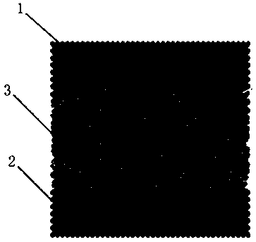
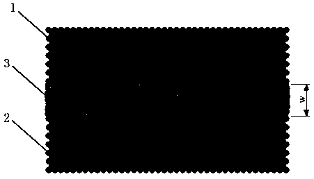
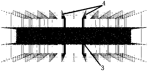

Image

  • A method for optimizing hydraulic fracturing proppant parameters
  • A method for optimizing hydraulic fracturing proppant parameters
  • A method for optimizing hydraulic fracturing proppant parameters

Examples


Embodiment Construction

[0028] The present invention will be further described below in conjunction with accompanying drawing, protection scope of the present invention is not limited to the following:

[0029] A hydraulic fracturing proppant parameter optimization method, it comprises the following steps:

[0030] S1. According to the geological conditions and mechanical characteristics of the rock formation, establish a rock formation-proppant-rock formation physical model that restores the true size of the proppant. The specific method of establishing the rock formation-proppant-rock formation physical model is as follows: establish a triaxial test model, make the rock formation and proppant model present different macroscopic physical properties by changing the physical parameters of the particles in the model, and make the macroscopic physical properties of the triaxial test model Checking with the macroscopic mechanical parameters of the laboratory triaxial test can determine the physical param...


PUM


Abstract

The invention discloses a hydro-fracture propping agent parameter optimization method. The method comprises the following steps of: S1, establishing a physical model for reducing the real size of a propping agent; S2, applying closing pressure on the surfaces of an upper rock stratum and a lower rock stratum of the model, wherein the difference between average heights of fracture surface particles of the upper rock stratum and the lower rock stratum is a fracture closing width w; S3, carrying out flow field grid discretization on a filling layer to ensure that the propping agent is wrapped by a flow field, and setting a viscosity and a density of a fluid and pressure of the fluid at two ends of the flow field; S4, calculating a total flow q of the flow field; S5, calculating a penetration rate and a flow conductivity; S6, changing parameters of the propping agent, and calculating and comparing the flow conductivities under different parameter combinations; and S7, carrying out optimizing by combining laboratory flow conductivity effect evaluations and on-site model selection experiments to obtain a final parameter combination. The method disclosed by the invention has the beneficial effects of being low in laboratory cost, being capable of testing flow conductivities of different types of propping agents, really reflecting the flow conductivities of formation fluids, and correctly and efficiently predicting the flow conductivities of propping agents under different geological conditions.

Description

technical field [0001] The invention relates to the field of oil and natural gas development, in particular to a hydraulic fracturing proppant parameter optimization method. Background technique [0002] At present, the proppant type selection method for a specific reservoir is mostly an experimental optimization method. Bai Qunshan listed in detail the optimal combination of proppants from the perspectives of fracturing well depth, oil displacement type, and whether the well is prone to sand production, but it only considered the applicability of different types of proppants, and did not consider the physical characteristics of oil and gas reservoirs. Determine the physical parameters of the proppant (Bai Qunshan. Design optimization and application of fracturing proppant in Sanan Development Zone [A].. "Oil Production Engineering" Volume 3 Volume 4 [C].:, 2013: 6). Guo Tiankui et al. conducted sand invasion experiments on formation sands with two different particle size c...

Claims


Application Information

Patent Timeline
Patent Type & Authority Patents(China)
IPC IPC(8): G06F17/50G06Q50/02E21B43/267
CPCE21B43/267G06F30/20G06Q50/02
Inventor 朱海燕沈佳栋唐煊赫陶雷高庆庆
Owner SOUTHWEST PETROLEUM UNIV
Learn More