A kind of oblique pull cutting machine

A cutting machine and oblique pulling technology, applied in metal sawing equipment, metal processing equipment, manufacturing tools, etc., can solve the difficulty of locking the crank arm, the difficulty in adjusting the angle between the crank arm and the working plate, and the difficulty in adjusting the angle of the working plate base, etc. problem, to achieve the effect of high adjustment accuracy

Active Publication Date: 2019-02-05
ZHEJIANG JINGSHEN IND
View PDF7 Cites 0 Cited by
  • Summary
  • Abstract
  • Description
  • Claims
  • Application Information

AI Technical Summary

Problems solved by technology

[0005] The present invention aims at the disadvantages in the prior art that the crank arm is difficult to lock, the angle between the crank arm and the working disc is difficult to adjust, and the angle of the working disc relative to the base is difficult to adjust, and provides an oblique pull cutting machine

Method used


Image

  • A kind of oblique pull cutting machine
  • A kind of oblique pull cutting machine
  • A kind of oblique pull cutting machine

Examples


Embodiment 1

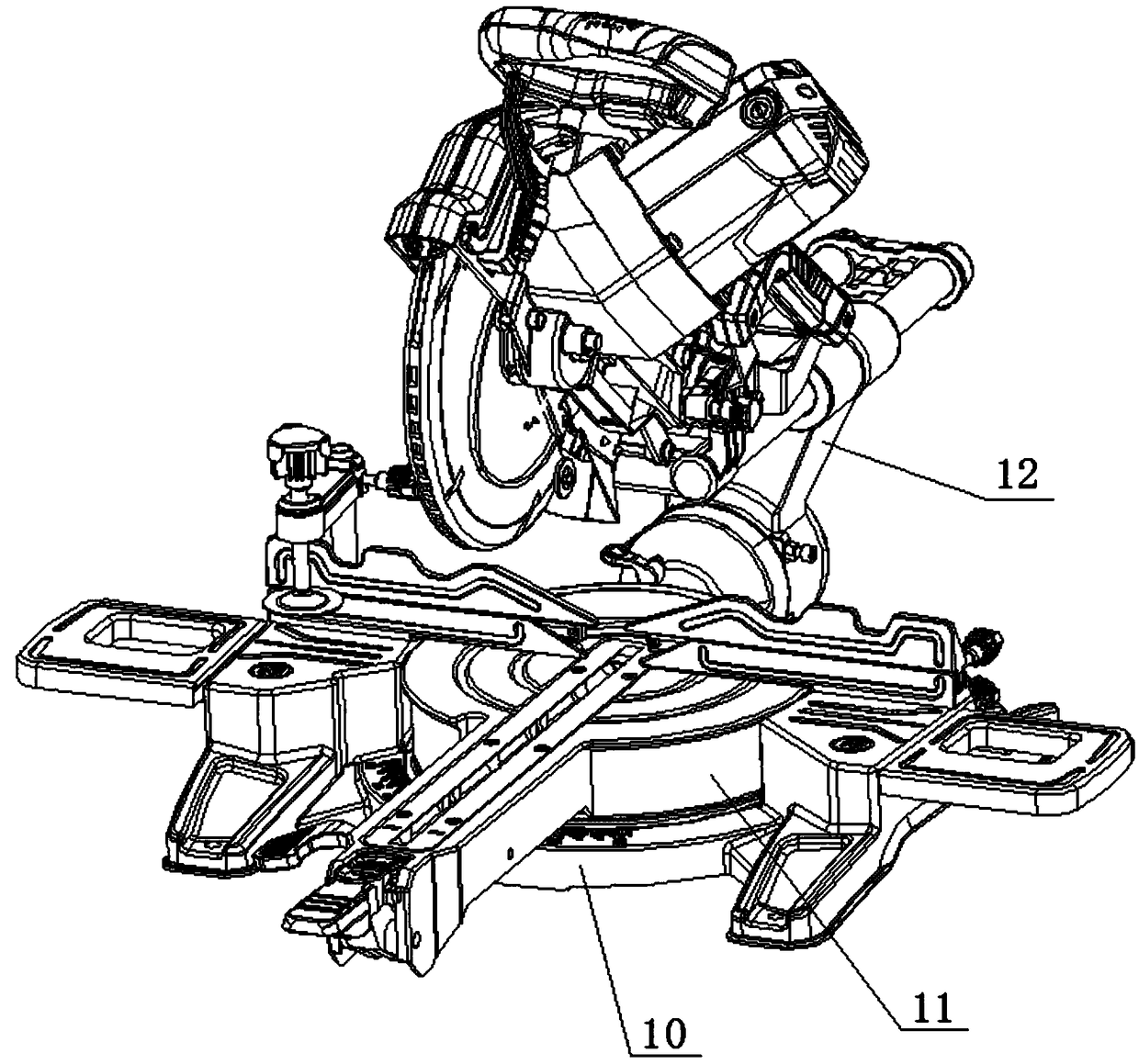
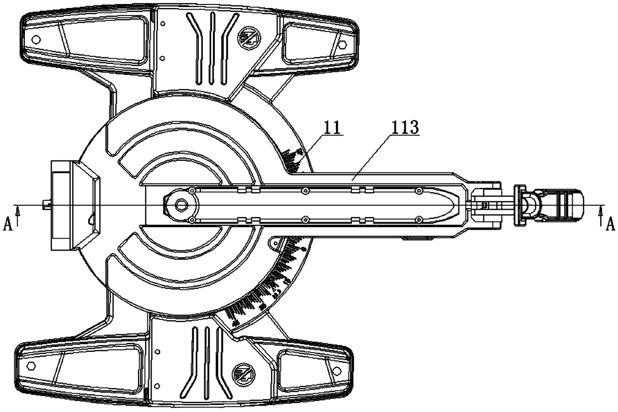
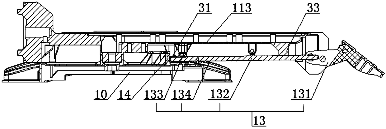
[0045] A kind of oblique pull cutting machine, such as Figure 1-18 As shown, it includes a base 10, a working disk 11 and a curved arm 12. The working disk 11 is installed on the base 10. The working disk 11 includes a first disc 111, a second disc 112 and a rotating handle 113. The second disc 112 and Rotating handles 113 are all fixed on the outer peripheral sidewall of the first disc 111, the second disc 112 and the rotating handle 113 are arranged oppositely, the curved arm 12 is connected with the second disc 112, and the working disc 11 is provided with a locking work. The first locking device 13 of the disc 11 and the base 10, the first locking device 13 includes a first locking button 131 and a first locking rod 132, the first locking button 131 is connected with the first locking rod 132, and the base 10 is fixed with a vertically upwardly protruding positioning piece 14, press the first locking button 131, and the top of the first locking rod 132 presses against the...


PUM


Abstract

The invention relates to a cutting machine, and discloses a cable-stayed cutting machine. The cable-stayed cutting machine comprises a base, a working disc and a crank arm. The working disc is mounted on the base and comprises a first disc, a second disc and a rotating handle. The second disc and the rotating handle are fixed to the side wall of the outer circumference of the first disc and are arranged oppositely. The crank arm and the second disc are connected. A first locking device for locking the working disc and the base is arranged below the working disc. The first locking device comprises a first locking button and a first locking rod, and the first locking button and the first locking rod are connected. A locating sheet protruding vertically upwards is fixed to the base. The first locking button is pressed down, and the top end of the first locking rod abuts against the side wall of the locating sheet for friction locking. In the cable-stayed cutting machine, the working disc can be locked on the base through the first locking device, the first locking rod is adopted for abutting against the locating sheet of the base for friction locking, an operator can conveniently adjust the angle of the working disc on the base, 1-degree adjustment can be carried out on the angle, and the adjusting precision is high.

Description

technical field [0001] The invention relates to a cutting machine, in particular to an oblique-stay cutting machine. Background technique [0002] A miter saw is a commonly used electric tool, which is mainly used to cut obliquely at a certain angle. [0003] A general miter saw includes a curved arm and a disc, and the miter is mainly to form a certain inclination angle between the curved arm and the disc, so that the knife saw on the miter saw can miter the object. Currently on the market Miter saw angle adjustment is more cumbersome. [0004] At the same time, when the miter saw is cutting obliquely, it is troublesome to adjust the angle of the miter saw, and it is difficult to lock the miter saw after the angle is adjusted. Contents of the invention [0005] Aiming at the disadvantages in the prior art that the crank arm is difficult to lock, the angle between the crank arm and the work disk is difficult to adjust, and the angle of the work disk relative to the base ...

Claims


Application Information

Patent Timeline
Patent Type & Authority Patents(China)
IPC IPC(8): B23D45/14
CPCB23D45/14
Inventor 叶伟豪徐明岐黄坤
Owner ZHEJIANG JINGSHEN IND
Why Eureka
Try Eureka