
Left and right rotating adjusting mechanism for fan

A technology that rotates left and right and adjusts the mechanism. It is applied in the direction of machine/engine, mechanical equipment, pump control, etc. It can solve the problem of increased wind resistance of the fan and achieve the effect of simple structure.

Inactive Publication Date: 2012-04-18
王宁雷
View PDF0 Cites 0 Cited by
  • Summary
  • Abstract
  • Description
  • Claims
  • Application Information

AI Technical Summary

Problems solved by technology

But the disadvantage is that the wind resistance when the fan is blowing out the wind is greatly increased.

Method used


Image

  • Left and right rotating adjusting mechanism for fan
  • Left and right rotating adjusting mechanism for fan
  • Left and right rotating adjusting mechanism for fan

Examples


Embodiment Construction

[0013] Below in conjunction with accompanying drawing and specific embodiment the present invention is described in further detail:

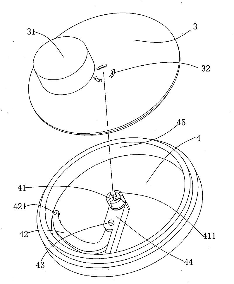
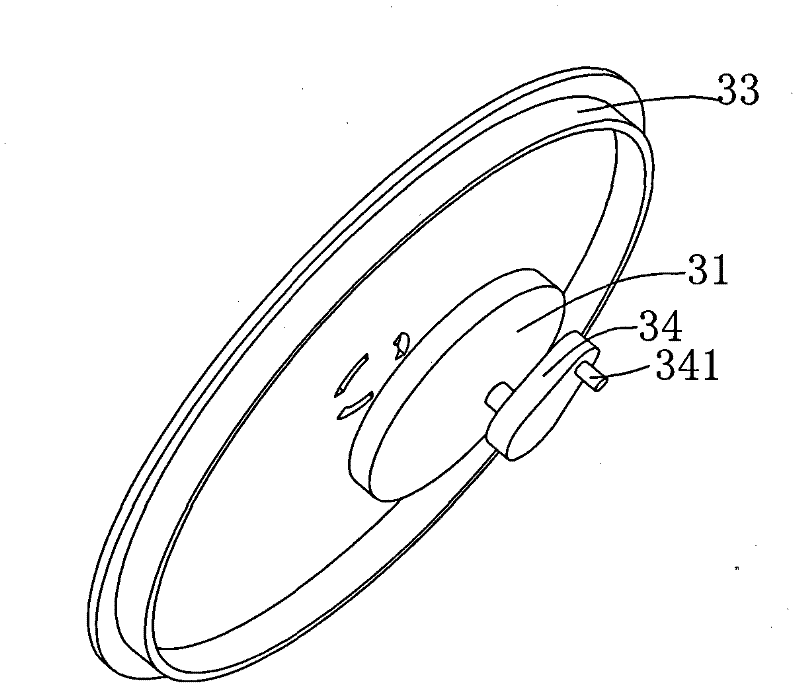
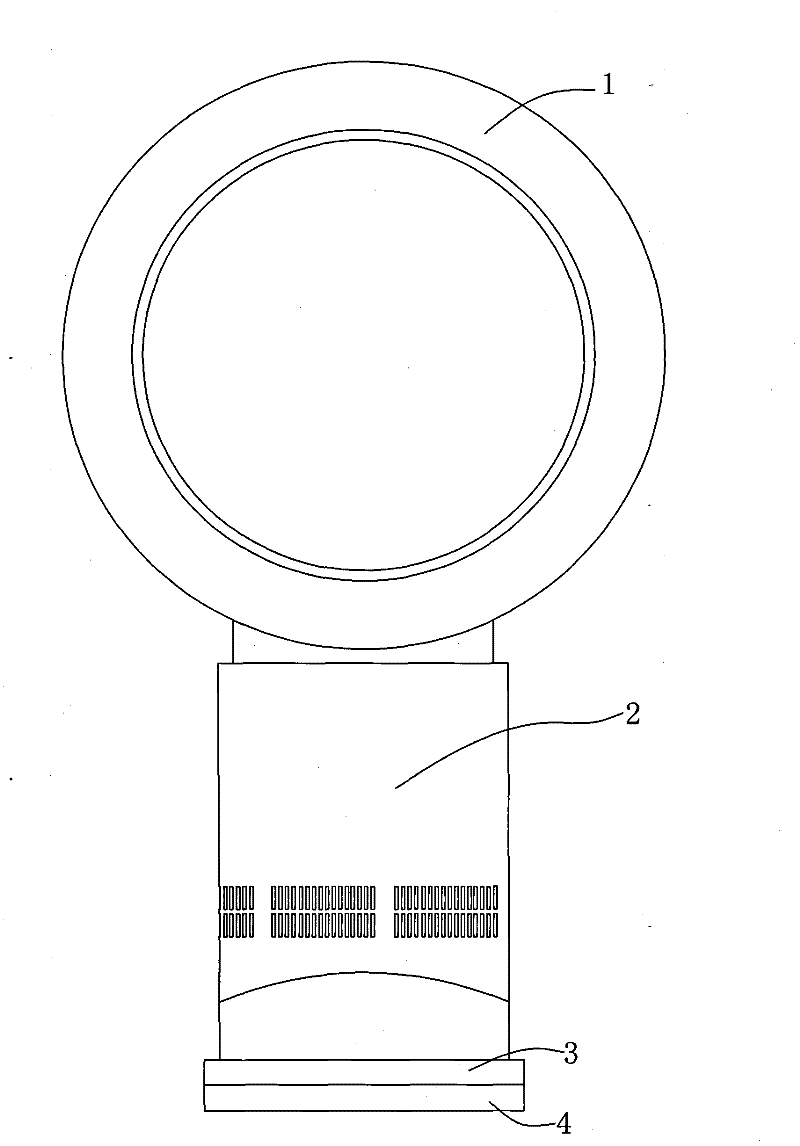
[0014] see figure 1 and figure 2 , The fan left and right rotation adjustment mechanism includes a base, the base includes an upper base 3 and a lower base 4, and the upper base 3 and the lower base 4 are both cylindrical. The upper base 3 is provided with a slot 32, the upper base 3 is fixed with a motor 31, the output shaft of the motor 31 is fixed to one end of the connector 34, and the other end of the connector 34 is provided with a hinged shaft armor 341, The hinge armor 341 passes through the hinge hole 421 on the connecting rod 42 to hinge the connecting piece 34 and one end of the connecting rod 42 together.

[0015] The lower base 4 includes a projection 44 and a rotating part 41, one end of the projection 44 passes through the center of the lower base 4, and the rotating part 41 is rotatably connected to the place where the axis of...


PUM


Abstract

The invention discloses a left and right rotating adjusting mechanism for a fan and belongs to the technical field of fans. The mechanism comprises a base, wherein the base comprises an upper base and a lower base; the upper base is rotationally connected with the lower base; a motor is fixed on the upper base; an output shaft of the motor is fixed with one end of a connecting piece; the other end of the connecting piece is hinged with one end of a connecting rod; and the other end of the connecting rod is hinged on the lower base. The motor is subjected to reaction force of the connecting piece while driving the connecting piece to rotate, and the upper base is pushed to rotate relative to the lower base so as to rotate the fan left and right. The mechanism has a simple structure, and wind resistance is not formed during air exhaust of the fan.

Description

technical field [0001] The invention belongs to the technical field of fans, in particular to a fan left and right rotation adjustment mechanism for adjusting the left and right rotation of the fan. Background technique [0002] There is a certain angle range for the fan to blow air, so when there are many people using the fan, some people will not be able to blow it. In order to solve this problem, the fan is generally equipped with a left and right rotation mechanism. The left and right rotation mechanism of the fan can drive the fan head to rotate back and forth, so that all people within a certain angle range can be blown to. At present, there is also a fan with a reversing piece installed on the air outlet side of the fan head. The reversing piece is provided with a baffle at a certain angle to the air outlet direction. There are openings between the baffles. Rotating with the fan blades, the airflow blown out by the fan passes through the port, is reversed by the reve...

Claims


Application Information

Patent Timeline
IPC IPC(8): F04D25/10F04D27/00
Inventor 王宁雷
Owner 王宁雷
Learn More