Garbage can

A trash can and lid technology, applied in the field of trash cans, can solve the problems of large volume of domestic garbage, easy to fall out of garbage, and less garbage, and achieve the effect of convenient movement, small occupied space, and increased stability

CN107089456AInactive Publication Date: 2017-08-25严世君
5 Cites 0 Cited by

Patent Information

Authority / Receiving Office
CN · China
Patent Type
Applications(China)
Current Assignee / Owner
Publication Date
2017-08-25
Estimated Expiration
Not applicable · inactive patent

Smart Images

  • Figure 1
    Figure 1
  • Figure 2
    Figure 2
  • Figure 3
    Figure 3
Patent Text Reader

Abstract

The invention relates to the technical field of cleaning tools, and in particular to a garbage can. The garbage can comprises a can body, wherein a can cavity is arranged in the can body; a can cover is arranged at an opening of the can cavity; one end of the can cover is hinged on the outer wall of the can body; a through hole is formed in the center of the can cover; a threaded hole is arranged at the lower part of the through hole and the diameter of the threaded hole is greater than that of the through hole; a round rod movably penetrates the through hole and a through groove is arranged in the top end of the round rod; a horizontal shaft barrel is arranged between two side walls of the through groove; a movable rod is rotatably sleeved on the horizontal shaft barrel; an external thread is arranged on the circumference of the bottom end of the round rod and matched with the threaded hole; a pressure plate is arranged below the round rod and is parallel to the can cover; a coaxial annular clamp groove is arranged in the top surface of the pressure plate; a magnet ring is arranged in the clamp groove; a baffle cover is arranged at an opening of the clamp groove; an iron ring for being attracted by the magnet ring is correspondingly arranged on the bottom surface of the can cover and is located in another clamp groove and baffle cover; a convex edge is arranged on the circumference of the bottom edge of the can body; and a clamp for clamping the movable rod is arranged on the can cover. The garbage can disclosed by the invention is capable of effectively compacting garbage.
Need to check novelty before this filing date? Find Prior Art

Description

technical field

[0001] The invention relates to the technical field of cleaning tools, in particular to a trash can. Background technique

[0002] Garbage disposer has another name called litter box or dustbin, is exactly the place where rubbish is installed. Most of the garbage cans are made of metal or plastic, and they are put into plastic bags when used. When there is too much garbage, the bags can be tied up and thrown away. Most trash cans have lids to prevent the smell of garbage from spreading, and some trash cans can be opened with a foot pedal.

[0003] At present, there are many types of trash cans, which can be divided into public trash cans and household trash cans in terms of usage occasions. When household trash cans hold garbage, some domestic garbage is relatively large, resulting in less garbage in household trash cans. When using, people often use feet or tools to compact the garbage in order to hold more garbage, so that the lid needs to be opened, and ...

Examples

Embodiment 1

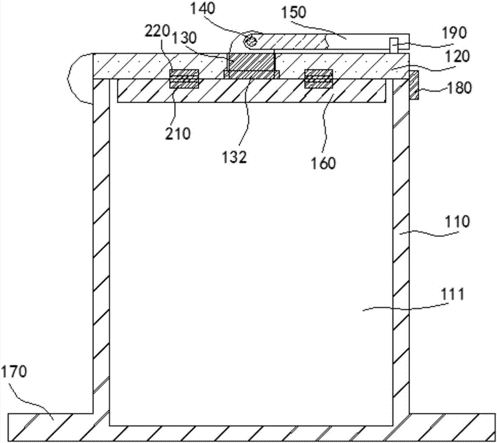
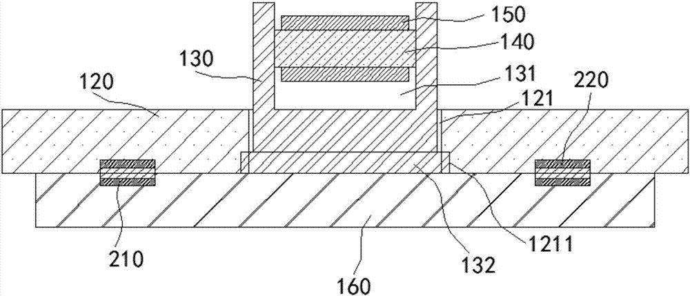
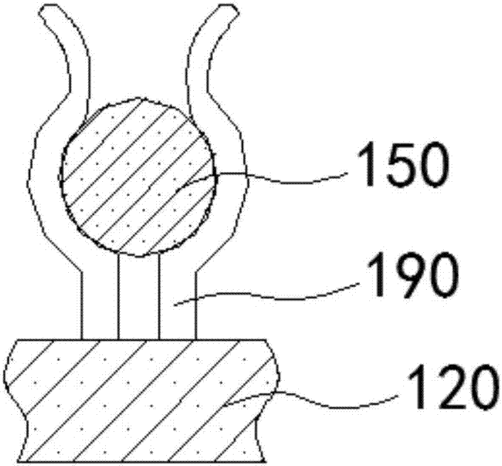
[0027] Such as figure 1 , figure 2 and image 3 As shown, the present embodiment provides a trash can, including a barrel body 110, a barrel cavity 111 is arranged in the barrel body 110, a barrel cover 120 is arranged at the mouth of the barrel cavity 111, and one end of the barrel cover 120 is hinged on the outer wall of the barrel body 110 On; the center of the bung 120 is provided with a through hole 121, the lower opening of the through hole 121 is a threaded hole 1211 and the diameter of the threaded hole 1211 is larger than the diameter of the through hole 121, a round rod 130 can move through the through hole 121 and the top is provided with Through groove 131, a horizontal shaft cylinder 140 is arranged between the two side walls of the through groove 131, and a movable rod 150 is rotatably sleeved on the horizontal shaft cylinder 140; the bottom end of the round rod 130 is circumferentially provided with an external thread 132, and the external thread 132 and the s...