Angular velocity sensor modeling method based on Magneto-hydrodynamic Effects

A magnetohydrodynamics, angular velocity sensor technology, applied in instruments, special data processing applications, electrical digital data processing, etc., can solve problems such as high unit price, improved measurement accuracy, and unsuitable for civil application development.

Active Publication Date: 2017-08-25
SHANGHAI AEROSPACE CONTROL TECH INST
View PDF7 Cites 9 Cited by
  • Summary
  • Abstract
  • Description
  • Claims
  • Application Information

AI Technical Summary

Benefits of technology

In this new technology that uses magnetic hydromodynamics (MHD), an angle speed sensor has been developed by creating different models from each other called these MWDs or transducers. These models help researchers better predict how well they will function when used with their equipment. By analyzing them accurately overall, we aimed at improving our performance capabilities and efficiency in developing MEMS devices such as accelerometers and gyroscopes.

Problems solved by technology

Technological Problem addressed by these inventions relates to improving the accuracy and resolution of measuring cameras with respect to orientation changes caused by external factors such as gravity or other forces on the ground surface (the satellites). Current solutions involve multiple types of measurements that require complex calculations involving many different components like accelerometers and magneto-rhynchoid devices. Additionally, current techniques have limitations due to their complexity and cost issues related to the use of specialized equipment needed for each component separately.

Method used


Image

  • Angular velocity sensor modeling method based on Magneto-hydrodynamic Effects
  • Angular velocity sensor modeling method based on Magneto-hydrodynamic Effects
  • Angular velocity sensor modeling method based on Magneto-hydrodynamic Effects

Examples


Embodiment Construction

[0039] The present invention will be further described below through specific embodiments in conjunction with the accompanying drawings. These embodiments are only used to illustrate the present invention, and are not intended to limit the protection scope of the present invention.

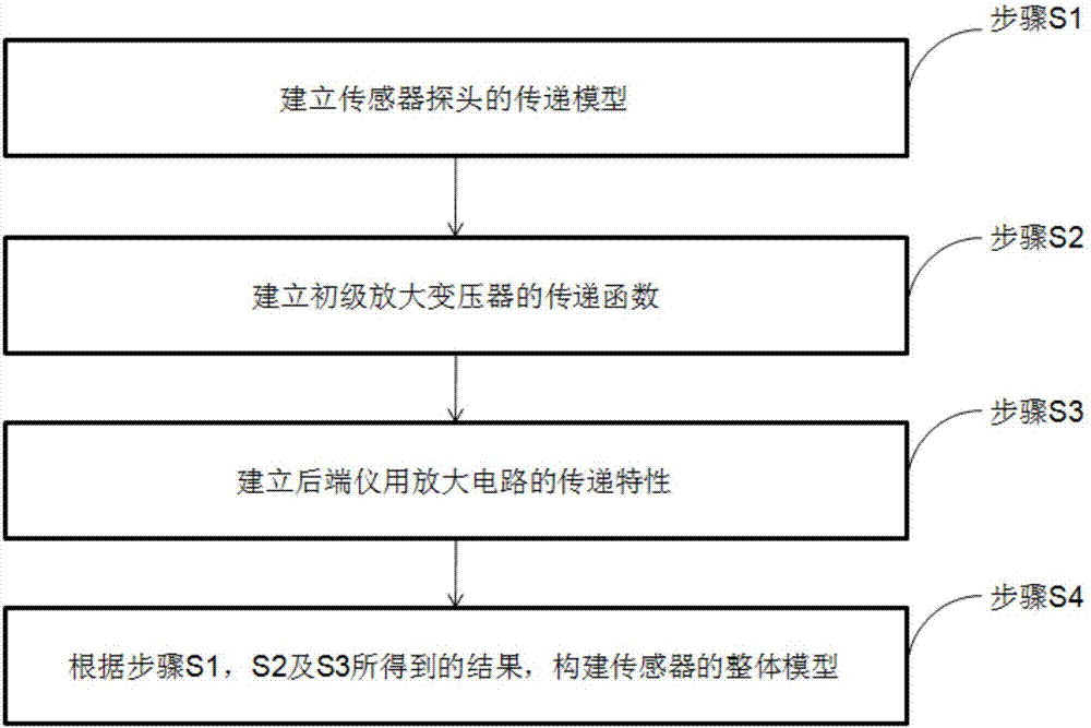
[0040] Such as figure 1 As shown, the present invention provides a kind of angular velocity sensor modeling method based on magnetohydrodynamic effect, comprises the following steps:

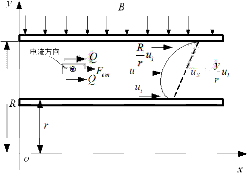
[0041] Step S1, establishing a transfer model of the sensor probe;

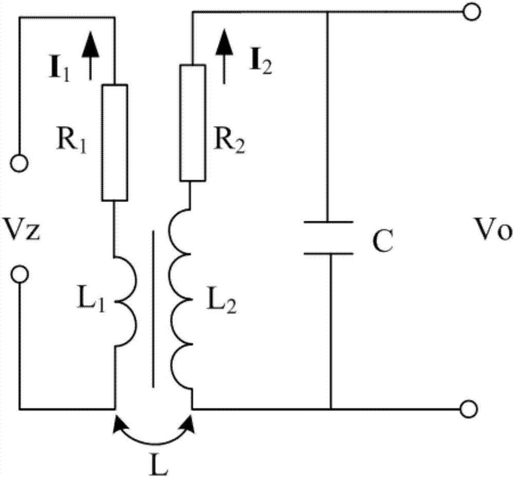
[0042] Step S2, establishing the transfer function of the primary amplifying transformer;

[0043] Step S3, establishing the transfer characteristics of the back-end instrument amplifier circuit;

[0044] Step S4, according to the results obtained in steps S1, S2 and S3, construct an overall model of the sensor.

[0045] The above-mentioned angular velocity sensor modeling method based on the magnetohydrodynamic effect, wherein the step S1 speci...


PUM


Abstract

The present invention discloses an angular velocity sensor modeling method based on Magneto-hydrodynamic Effects. The method comprises the following steps: step S1. establishing a transfer model of a sensor probe; step S2. establishing a transfer function of a primary amplification transformer; step S3. establishing a transfer characteristic of a rear-end instrument amplification circuit; and step S4. according to a result obtained in steps S1, S2 and S3, constructing an overall model of a sensor. The method disclosed by the present invention systematically gives a sensor probe model, a transformer model, a rear-end amplification circuit model and a sensor full-process model made of the three models. The method can quantitatively analyze a frequency response characteristic corresponding to the sensor under certain design parameters; and by means of the transfer model thereof, perform optimization, type selection and design on related parameters in the sensor, so as to instruct actual research and development of sensors.

Description


Claims


Application Information

Patent Timeline
Owner SHANGHAI AEROSPACE CONTROL TECH INST
Why Eureka
Try Eureka