Counter-gravity casting riser tube positioning mechanism

A technology of anti-gravity casting and positioning mechanism, which is applied to casting equipment, manufacturing tools, and equipment for feeding molten metal into molds, etc., and can solve problems such as deviation of riser pipes and gaskets, and pouring failures

Active Publication Date: 2017-08-29
HARBIN INST OF TECH
View PDF12 Cites 8 Cited by
  • Summary
  • Abstract
  • Description
  • Claims
  • Application Information

AI Technical Summary

Problems solved by technology

[0004] The purpose of the present invention is to solve the technical problem that the existing method easily causes the liquid riser and the sealing gasket (ring) to deviate, thereby resulting in pouring failure, and provides a positioning mechanism for the anti-gravity casting liquid riser

Method used


Image

  • Counter-gravity casting riser tube positioning mechanism
  • Counter-gravity casting riser tube positioning mechanism
  • Counter-gravity casting riser tube positioning mechanism

Examples


specific Embodiment approach 1

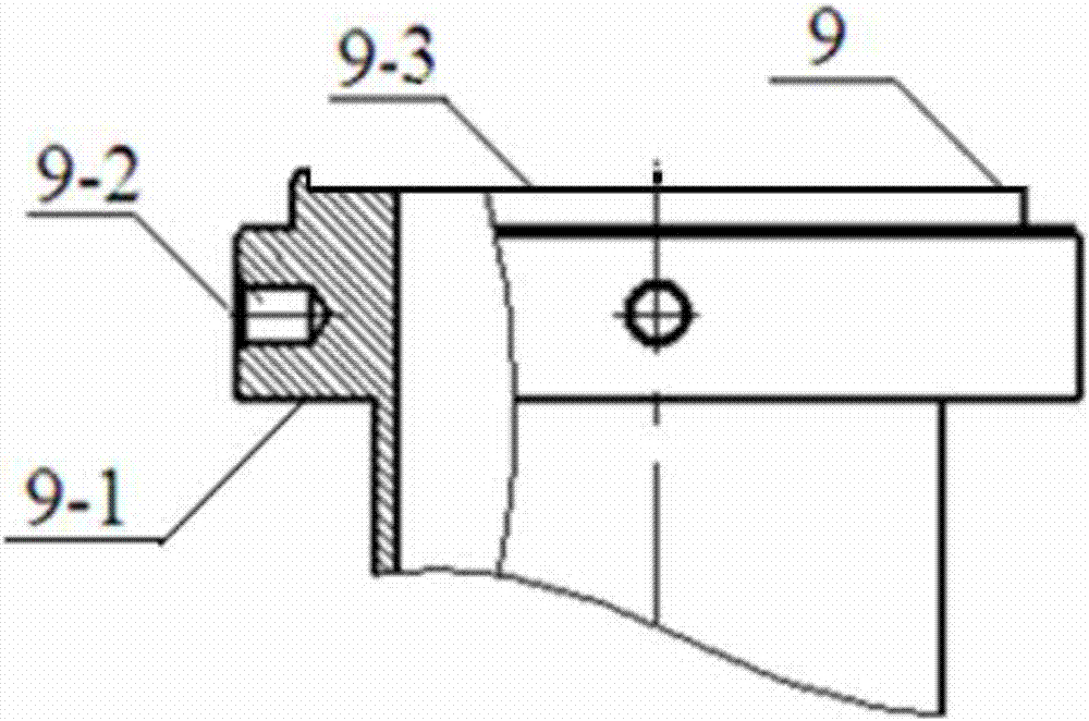
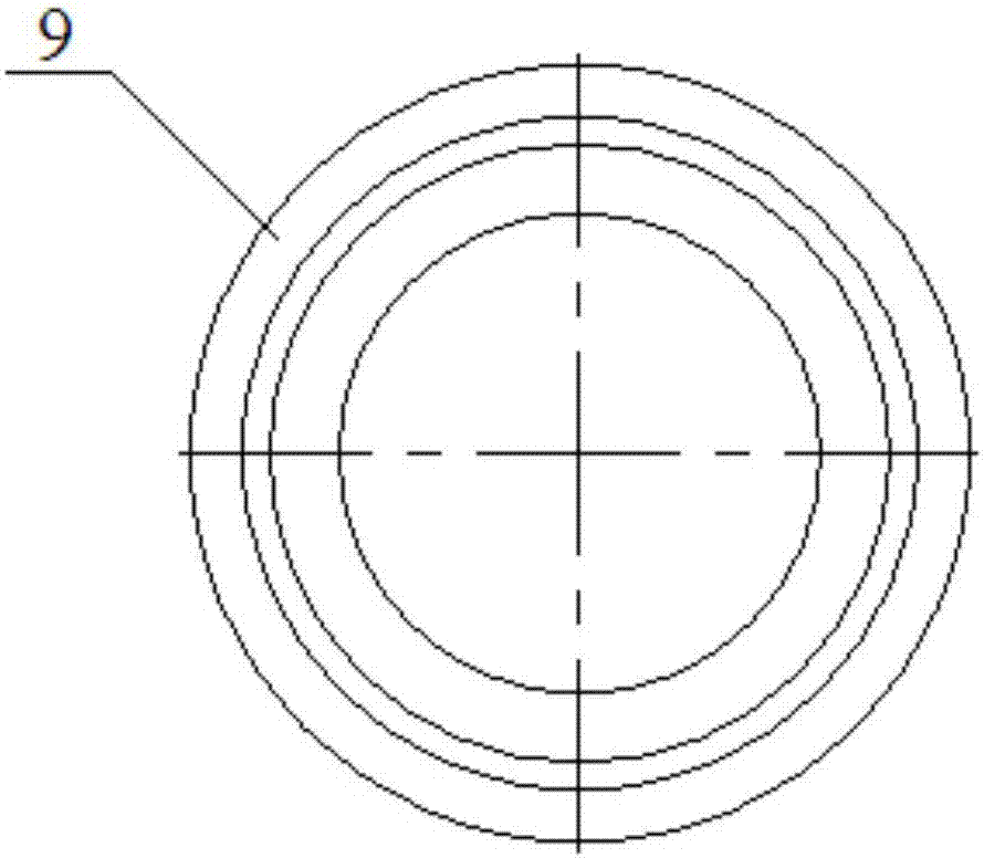
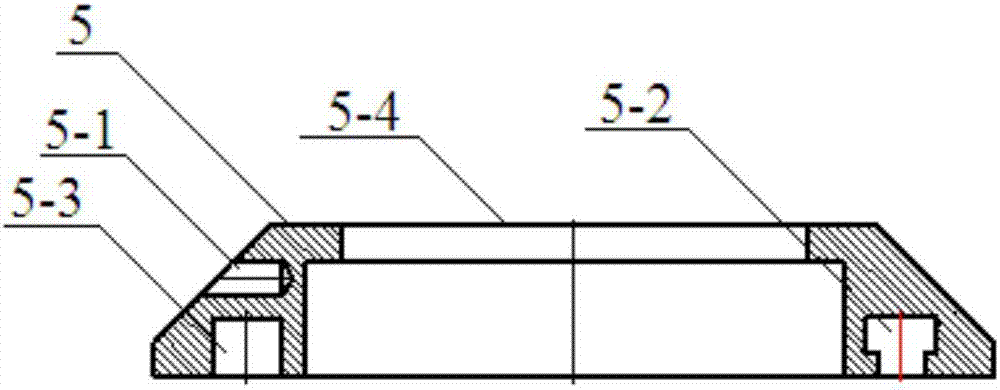
[0017] Specific implementation mode 1: In this embodiment, the anti-gravity casting riser pipe positioning mechanism is set up in sequence from top to bottom with the mold 1, the upper sealing gasket 4 of the riser pipe, the positioning ring 5, the middle partition plate 6, the positioning bolt 7, and the riser pipe The lower sealing gasket 8 and the riser pipe 9, the riser pipe 9 is fixed on the intermediate partition 6 by the positioning ring 5 and the positioning bolt 7, the upper end of the riser pipe 9 is provided with a flange 9-1, and the flange 9-1 The side surface is provided with a hoisting port 9-2, the top of the flange 9-1 is provided with a limit groove 9-3, the sealing gasket 4 on the riser pipe is matched with the limit groove 9-3, and the upper part of the positioning ring 5 is a conical platform, positioning The lower section of the ring 5 is a cylindrical platform, and a hoisting hole 5-1 is provided on the side of the conical platform. The cavity 2 is locate...

specific Embodiment approach 2

[0018] Embodiment 2: This embodiment differs from Embodiment 1 in that the positioning ring 5 is provided with a central stepped hole 5-4, and the flange 9-1 cooperates with the central stepped hole 5-4. Others are the same as in the first embodiment.

specific Embodiment approach 3

[0019] Specific embodiment three: the difference between this embodiment and specific embodiment one or two is that there are four positioning slots 5-2 and positioning bolt inlet and outlet 5-3 under the cylindrical platform, and the positioning slots 5- 2 communicate with the set bolt inlet and outlet 5-3. Others are the same as those in the first or second embodiment.


PUM


Abstract

The invention relates to a counter-gravity casting riser tube positioning mechanism, and aims to solve the technical problems that deviation of a riser tube and a sealing gasket (ring) is easily caused by an existing method, and then failing of pouring is caused. A casting mold 1, a cavity 2, a sprue gate 3, a riser tube upper sealing gasket 4, a positioning ring 5, a middle partition 6, a positioning bolt 7, a riser tube lower sealing gasket 8 and a riser tube 9 are successively arranged on the counter-gravity casting riser tube positioning mechanism from top to bottom, the riser tube 9 is fixed on the middle partition 6 through the positioning ring 5 and the positioning bolt 7, a flange 9-1 is arranged at the upper end of the riser tube 9, a hoisting opening 9-2 is formed in a side surface of the flange 9-1, the upper section of the positioning ring 5 is a conical table, the lower section of the positioning ring 5 is a cylindrical table, and a hoisting hole 5-1 is formed in a side surface of the conical table. According to the counter-gravity casting riser tube positioning mechanism, positioning is implemented by the positioning ring and the middle partition, therefore, the riser tube and the sealing gasket (ring) cannot deviate, and pouring can be successful. The invention belongs to the field of riser tube positioning mechanisms.

Description

technical field [0001] The invention relates to a positioning mechanism for an anti-gravity casting riser pipe. Background technique [0002] Anti-gravity casting (low pressure casting, differential pressure casting, vacuum suction casting and pressure regulating casting) is to make the pressure on the liquid surface of the metal in the crucible greater than the pressure in the mold cavity, and under the action of this pressure difference, the liquid metal is forced to The riser connected between the cavity and the crucible rises to fill the cavity. This type of casting method in which the molten metal flows against the direction of gravity and fills the cavity and solidifies is called anti-gravity casting. [0003] In the existing situation, the liquid riser used for pouring and filling is inserted into the liquid metal in the crucible of the holding furnace through the middle partition, and the flange plate at the upper end of the riser is clamped on the middle partition,...

Claims


Application Information

Patent Timeline
Patent Type & Authority Applications(China)
IPC IPC(8): B22D18/04B22D18/06B22D35/04
Inventor 孙剑飞曹福洋宁志良黄永江彭德林宋和谦
Owner HARBIN INST OF TECH
Why Eureka
Try Eureka