

Continuous foaming aluminum automatic production line
An automatic production line and foamed aluminum technology, which is applied to the equipment for feeding molten metal into the mold, metal processing equipment, casting equipment, etc. The problems of low discharge efficiency of foamed aluminum are achieved, and the effects of simple structure, cost saving and production efficiency improvement are achieved.
- Summary
- Abstract
- Description
- Claims
- Application Information
AI Technical Summary
Problems solved by technology
Method used
Image

Examples
Embodiment 1
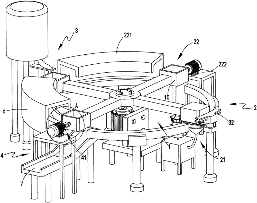
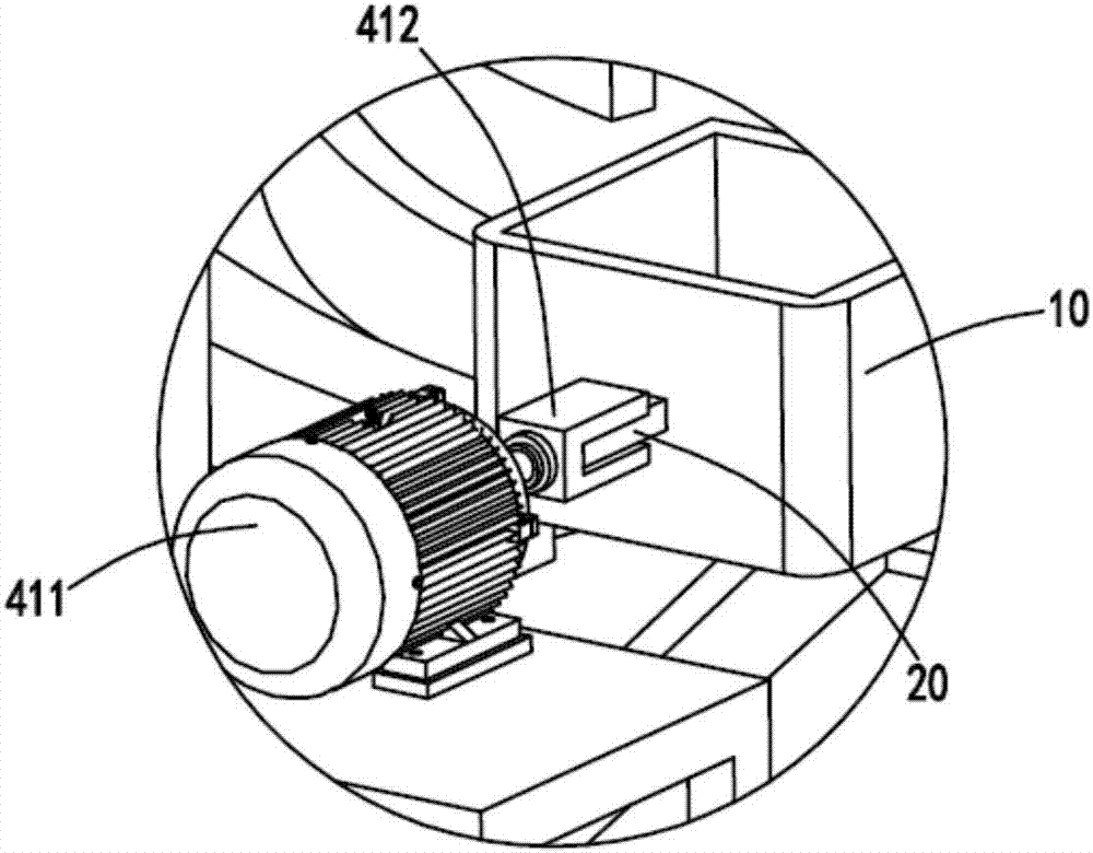
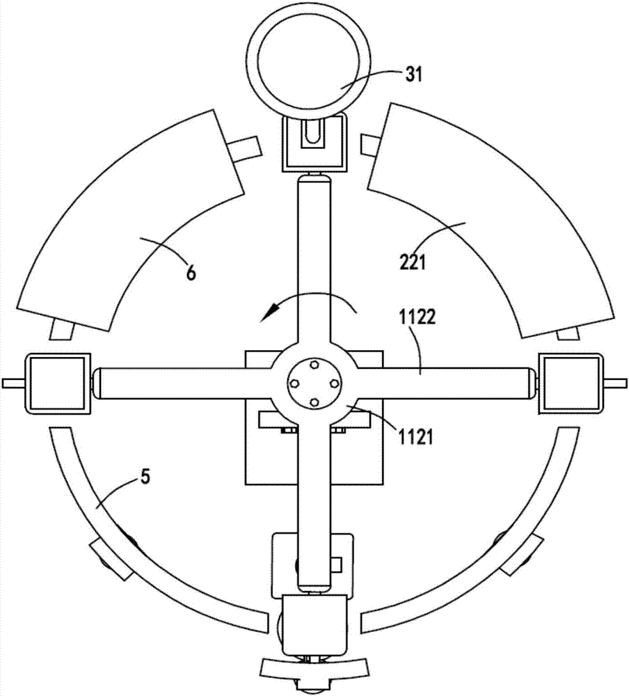
[0038] figure 1 It is a schematic diagram of the structure of the foamed aluminum rotary discharge equipment, figure 2 It is a schematic diagram of the enlarged structure of the turning device a, image 3 It is a schematic top view of part of the structure of the foamed aluminum rotary discharge equipment, Figure 4 Schematic diagram of the structure of the spraying mechanism, Figure 5 It is a schematic diagram of the enlarged structure of the liquid injection device and the power plant, Figure 6 Schematic diagram of the rotary mechanism. Such as figure 1 , figure 2 , image 3 , Figure 4 , Figure 5 and Figure 6 As shown, a continuous aluminum foaming automatic production line includes a rotating part 1, and the rotating part 1 includes a rotating mechanism 11, and the rotating mechanism 11 is used to drive a plurality of material receiving molds 10 to rotate, and the material receiving mold 10 A block 20 is arranged on the outer edge of the
[0039] The pretr...
Embodiment 2
[0057] Such as figure 1 , figure 2 , image 3 , Figure 4 , Figure 5 and Figure 6 As shown, the components that are the same as or corresponding to those in the first embodiment are marked with the corresponding reference numerals in the first embodiment. For the sake of simplicity, only the differences from the first embodiment will be described below. The difference between the second embodiment and the first embodiment is that: as a preference, a receiving hopper 8 is provided below the liquid spray head 2113, and the bottom of the receiving hopper 8 is connected to the liquid storage tank 2111 through the conduit b9. It is internally connected, and when the release agent is sprayed on the material receiving mold 10, it is inevitable that excess release agent will drip downward. The release agent collected by the hopper 8 is returned to the liquid storage tank 2111 for reuse, which saves resources.
[0058] Working process: The material receiving mold 10 can be rot...
PUM
 Abstract
Description
Claims
Application Information