Gun exchanging plate

A technology for changing gun disks and inclined surfaces, which is applied in the direction of manipulators and manufacturing tools to achieve good sealing performance

Active Publication Date: 2017-08-29
SHANGHAI SONCO QUICK CHANGE SYST
View PDF3 Cites 3 Cited by
  • Summary
  • Abstract
  • Description
  • Claims
  • Application Information

AI Technical Summary

Problems solved by technology

However, in some cases, such as strong vibration, impact or other external forces, the piston may move from the anti-disengagement contact surface to the release position
Also, in existi

Method used


Image

  • Gun exchanging plate
  • Gun exchanging plate
  • Gun exchanging plate

Examples


Embodiment 1

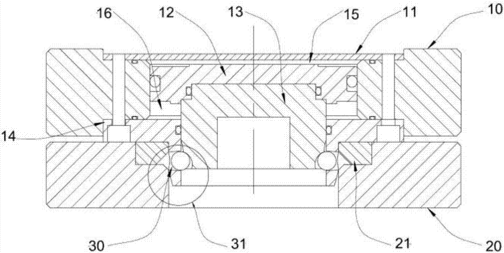
[0043] This embodiment discloses a gun changing disc, which includes a tool side and a main body side. Wherein, the main body side includes: a main body plate, a recess is provided on the main body plate, and a protrusion is arranged in the recess; a piston, the piston is a cavity structure with one end open and one end closed, and the piston is movably mounted on the protrusion. A ring of steel balls is provided at the opening end, and a first sealing cavity is formed between the piston and the main body plate; the piston cover is located in the inner cavity of the piston, and is fixed on the protrusion of the recess, forming a second sealing cavity with the piston; The flange includes an annular sheet structure and an extension part, the annular sheet structure is fixedly connected to one end of the main body plate, the extension part is arranged on the inner side of the annular sheet structure, and the extension part extends away from the main body plate, and the extension p...

Embodiment 2

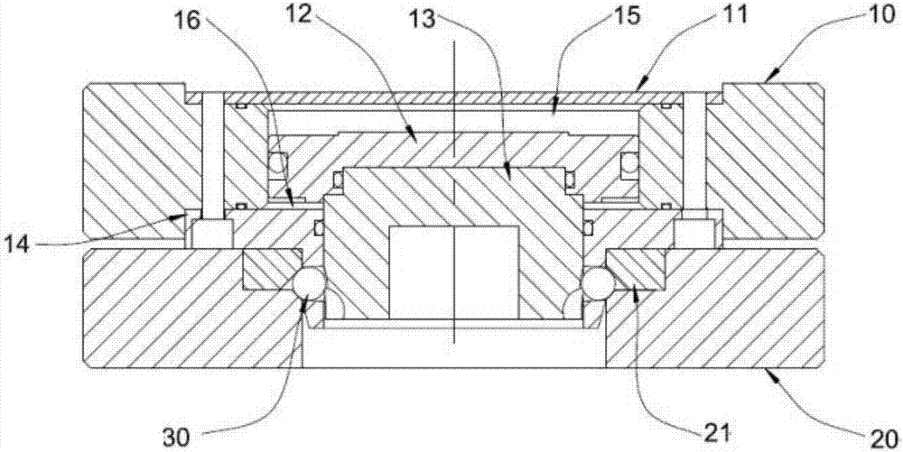
[0049] Embodiment 2 discloses another specific embodiment for changing the gun disk. Its structure is basically the same as Embodiment 1. The difference is that in this embodiment, an annular groove is provided on the tool plate. When the tool side is placed On the main body side, the end surface of the tool plate outside the annular groove is attached to the end surface of the annular sheet structure of the flange, and the extension of the flange and the opening end of the piston extend into the annular groove. Specifically, the bottom of the annular groove is provided with a through hole.

[0050] The annular groove in this embodiment can guide the movement of the piston to a certain extent, making the movement of the piston more stable, thereby ensuring the smooth locking and separation of the tool side and the main body side, and the through hole at the bottom of the groove is convenient for the piston When moving in the groove, the air pressure in the groove is too high t...

Embodiment 3

[0052] Embodiment 3 discloses another specific embodiment of the gun changer, its structure is basically the same as Embodiment 1, the difference is that, in this embodiment, the second end of the extension part is provided with a third slope, and the third The inclined plane and the second inclined plane are located on the same side of the extension part, and the third inclined plane is opposite to the inclined direction of the second inclined plane. When the tool side is put into the main body side and is in a loose state, the third slope is located outside the steel ball, and the third slope can form a certain protection for the steel ball.

[0053] Specifically, the main body plate is provided with a fourth slope, the fourth slope is located inside the annular groove, and the fourth slope is facing the outside of the ring groove, and the fourth slope is opposite to the first slope and the direction of inclination is opposite. When the tool side is separated from the main b...


PUM


Abstract

The invention discloses a gun exchanging plate comprising a tool side and a main body side. The tool side comprises a tool board and locking rings. First inclined planes are arranged on the locking rings. The main body side comprises a main body board provided with a concave part, a piston with one end being open and the other end being closed, a piston cover and a flange. A bulge is arranged in the middle of the concave part. A circle of steel balls is arranged at the opening end of the piston, the piston is arranged on the bulge in a penetrating mode, and a first airtight cavity is formed between the piston and the main body board. The piston cover is located in the piston and fixed on the bulge, and the piston cover and the piston form a second airtight cavity. The flange comprises an annular flake structure and an extending part. The annular flake structure and the main body board are fixedly connected. A second inclined plane is arranged on the extending part. When the first airtight cavity is aerated, the tool side and the main body side are loosened. When the second aright cavity is aerated, the tool side and the main body side are locked. The steel balls are clamped by the first inclined planes and the second inclined plane with different inclination angles. The gun exchanging plate is safe and reliable in clamping mode, and the risk of disengagement of the main body side and the tool side at the time of clamping can be avoided.

Description

technical field [0001] The invention relates to the technical field of structural design of robots, in particular to a gun changing disk. Background technique [0002] The robot tool changer is mainly composed of two parts, which are divided into tool side and main body side. The main body side is generally fixed at the end of the robot, the tool side is connected to the tool, and the main body side can be used to replace different tools by clamping and loosening the tool side. Usually, in actual use, one body side corresponds to two or more sets of tool sides to achieve the purpose of tool replacement. [0003] At present, the clamping and loosening of the tool exchange device is realized by using the piston rod and the locking ring to clamp and loosen the steel ball, such as figure 1 , 2 As shown, the main body side is mainly composed of a main body plate 10, a stopper 11, a piston (piston cover 12 and a piston rod 13), a flange 14 and a steel ball 30, and the tool side...

Claims


Application Information

Patent Timeline
IPC IPC(8): B25J19/00
CPCB25J19/00
Inventor 赵红梅耿翔宇
Owner SHANGHAI SONCO QUICK CHANGE SYST
Why Eureka
Try Eureka