

Vernier caliper
A vernier caliper and depth gauge technology, applied in the field of vernier calipers, can solve the problems of easily changing the current position of the slider and affecting the reading of the vernier caliper
- Summary
- Abstract
- Description
- Claims
- Application Information
AI Technical Summary
Problems solved by technology
Method used
Image

Examples
Embodiment Construction
[0028] The above and other technical features and advantages of the present invention will be clearly and completely described below in conjunction with the accompanying drawings. Apparently, the described embodiments are only some of the embodiments of the present invention, not all of them.
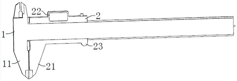
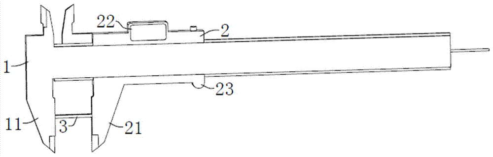
[0029] refer to Figure 1a , the present invention provides a vernier caliper, comprising a main scale 1 and a slider 2 slidingly connected to the main scale 1 . In the figure, there is a measuring claw 11 at the end of the main scale 1, and a measuring claw 21 at the end of the slider 2. These two measuring claws 11, 21 cooperate with each other to clamp the object 3 to be measured. in, Figure 1b It shows the state where the object 3 to be measured is clamped by the two measuring jaws 11 and 21 . In this state, the slider 2 has moved a certain distance along the length direction of the main ruler 1 . During normal use, the slider 2 can be driven to move along the length direction of...
PUM
 Abstract
Description
Claims
Application Information