English translation auxiliary device

An auxiliary device and translation technology, applied in the field of English translation devices, can solve the problem of increasing redundant actions of translators

Inactive Publication Date: 2018-11-13
HENAN UNIV OF URBAN CONSTR
View PDF20 Cites 1 Cited by
  • Summary
  • Abstract
  • Description
  • Claims
  • Application Information

AI Technical Summary

Problems solved by technology

[0004] However, in most cases, the line read by the translator does not constitute a complete sentence, but the next line or even the next two lines of text need to be read in combination, and due to the existence of a ruler, the next line or several lines of text should be read. In order to avoid occlusion, the translator needs to constantly move the ruler when translating to reveal the next line or lines of text, which will inevitably increase the extra actions of the translator

Method used


Image

  • English translation auxiliary device
  • English translation auxiliary device
  • English translation auxiliary device

Examples


Embodiment 1

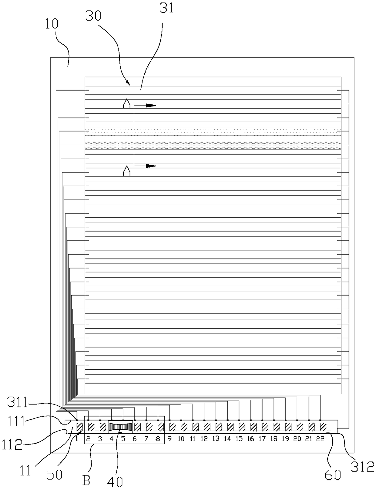
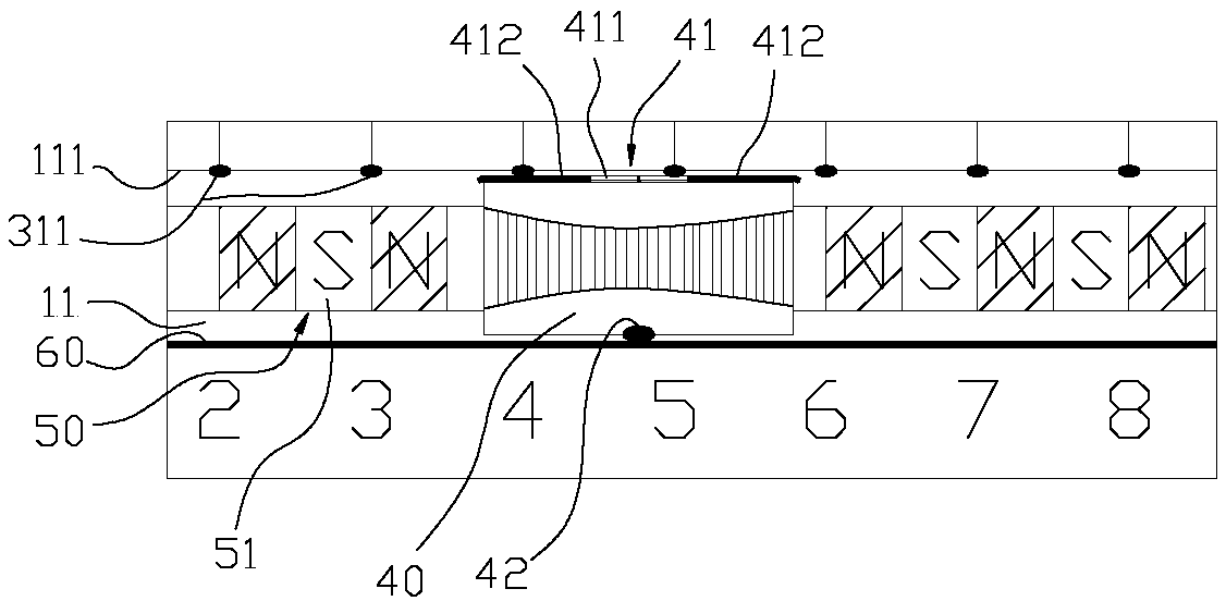
[0043] In this example, if Figures 2 to 6 As shown, the lower part of the front surface of the tablet 10 is provided with a laterally extending guide groove 11, and the positive electrode pins corresponding to the LED light strips 31 arranged in sequence from top to bottom are arranged in sequence from left to right, and are convex in turn. Out of the upper groove wall 111 of the guide groove 11; the lower groove wall 112 of the guide groove 11 is provided with a conductive plate 60, and the negative pins 312 of a plurality of LED light strips 31 are integrated into one and electrically connected to the left end of the conductive plate 60; The control assembly includes a push block 40 with a mounting cavity inside, the push block 40 is arranged in the guide groove 11 and can slide along the guide groove 11, the power supply is installed in the installation cavity of the push block 40, the power supply and the upper groove wall 111 of the guide groove 11 A slide plate 41 made ...

Embodiment 2

[0052] In this example, if Figure 7 with Figure 8 As shown, a sunken groove is provided at the lower position of the front of the tablet 10, and the positive electrode pins corresponding to the LED light-emitting strips 31 arranged sequentially from top to bottom are arranged circumferentially along the groove wall of the sunken groove, and protrude On the tank wall of the sinking tank, the negative electrode pins of a plurality of LED lighting strips 31 are integrated into one and extend into the center of the tank bottom of the sinking tank; the control assembly includes a knob 80 with a mounting cavity inside, and the lower end of the knob 80 extends into To the sinker, the outer wall of the part where the knob 80 protrudes into the sinker is attached with a curved plate 82 made of conductive material, the power supply is installed in the installation cavity of the knob 80, and the positive pole of the power supply passes through the lead wire and the curved plate 82 ele...


PUM


Abstract

The invention discloses an English translation auxiliary device. The English translation auxiliary device comprises a flat panel, a support and retaining parts and further comprises a light-emitting assembly and a control assembly, wherein the support is in pivot joint with the back face of the flat panel; the retaining parts are used for enabling paper printed with English to be flatly spread onthe front face of the flat panel; the light-emitting assembly is disposed on the front face of the flat panel, and the paper is located on the light-emitting assembly; and the control assembly is usedfor controlling the light-emitting assembly so as to make the light-emitting assembly illuminate one random line of text or several random adjacent lines of texts in the paper and then highlight therandom line of text or the several random adjacent lines of texts through illumination. On the one hand, the line of text can be highlighted by being illuminated so that a translator can fast lock theto-be-translated line of text; and on the other hand, the lines of texts which are not illuminated are not covered so that the translator cannot be affected when the translator needs to read the other lines of texts which are not illuminated and the reading scope of the translator cannot be affected.

Description

technical field [0001] The invention relates to the technical field of English translation devices, in particular to an English translation auxiliary device. Background technique [0002] Translators usually use a translation aid (English translation holder) when translating paper foreign language documents. Specifically, the translation assistance device includes a flat panel and a bracket pivotally connected to the back surface of the flat panel, the bracket enables the flat panel to be placed obliquely, and the front side of the flat panel is used to place paper documents (the paper can be attached and kept on front). [0003] In order to prevent the translators from being serialized when reading the text, the translators can use the ruler to place it horizontally under the line of text to be read, so as to prevent themselves from being serialized when reading. [0004] However, in most cases, the line read by the translator does not constitute a complete sentence, but ...

Claims


Application Information

Patent Timeline
Patent Type & Authority Applications(China)
IPC IPC(8): B42D17/00B42D9/00
CPCB42D9/008B42D17/00
Inventor 董召锋王莉侯静雯尹国有韩杨吴佳宝景丽亚罗从双
Owner HENAN UNIV OF URBAN CONSTR
Why Eureka
Try Eureka