Magnetic suspension spherical flywheel imbalance vibration inhibition method

A magnetic levitation, spherical technology, applied in the direction of adaptive control, general control system, control/regulation system, etc., can solve problems such as the inability to guarantee the uniformity of mass distribution, reducing the control accuracy of the magnetic levitation spherical flywheel, and the unbalanced mass of the rotor.

Active Publication Date: 2017-08-29
BEIJING INSTITUTE OF PETROCHEMICAL TECHNOLOGY
View PDF7 Cites 11 Cited by
  • Summary
  • Abstract
  • Description
  • Claims
  • Application Information

AI Technical Summary

Problems solved by technology

The magnetic levitation spherical flywheel has a spherical rotor structure. Limited by the machining accuracy of the rotor, the center of mass of the rotor deviates from the center of the rotor sphere, resulting in eccentricity of the rotor. Due to the magnetic flux leakage in the radial/axial magnetic bearing, the magnetic density at the edge of the deflection magnetic bearing is uneven. Rotor eccentric moment, the rotor does not rotate around the geometric axis, the rotor will be affected by the disturbance force, and at the same time it will reduce the uniformity of the stator air

Method used


Image

  • Magnetic suspension spherical flywheel imbalance vibration inhibition method
  • Magnetic suspension spherical flywheel imbalance vibration inhibition method
  • Magnetic suspension spherical flywheel imbalance vibration inhibition method

Examples


Embodiment Construction

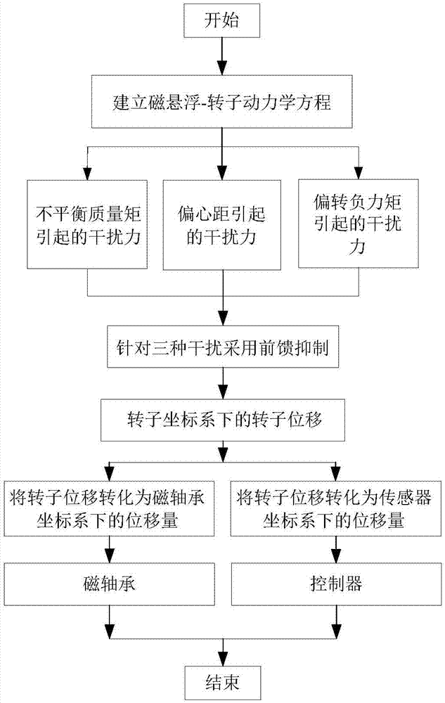
[0049] Such as figure 1 As shown, in the specific implementation process, the specific implementation steps of the present invention are as follows:

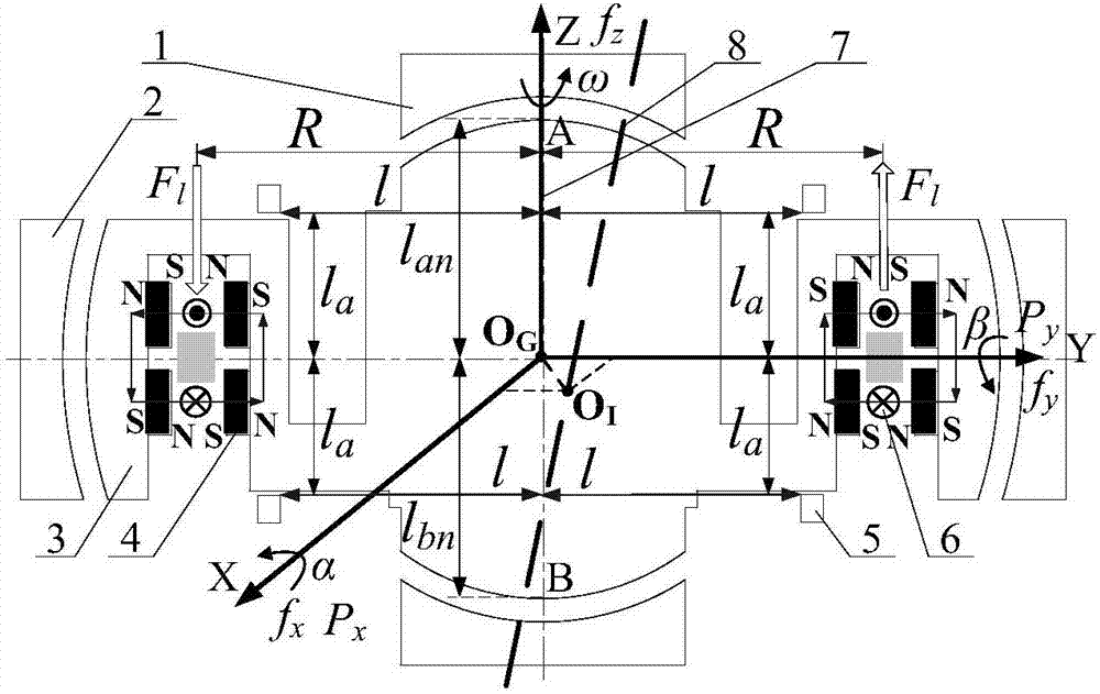
[0050] 1. According to Newton's second law and the gyroscope technical equation, the magnetic levitation spherical flywheel magnetic bearing-rotor dynamics equation is established as:

[0051]

[0052] simplified

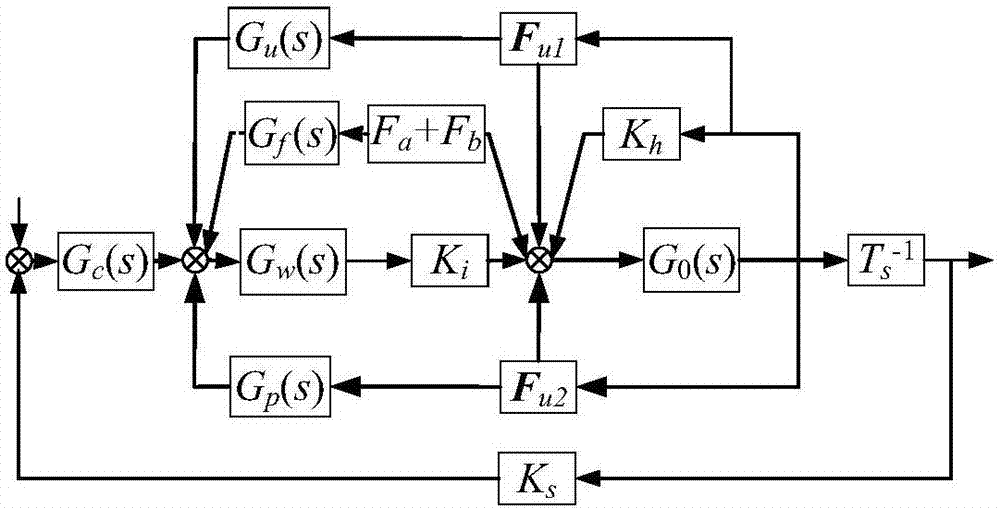
[0053] After linearizing the electromagnetic force of each suspension channel of the rotor, we get:

[0054]

[0055] Simplified to F m = K h q m +K i I

[0056] in,

[0057] M=[m J y j x m], q=[x β y -α z] T ,

[0058] F=[f x p y f y -p x f z ] T are mass matrix, gyroscope matrix, generalized coordinates and generalized force respectively; F m =[f x p y f y p x f z ] T is the electromagnetic force and moment acting on the rotor by the magnetic bearing; K h =diag[k hx 0k hy 0k hz ] is the displacement stiffness matrix of the magnetic bearing, k hx 、k hy 、k hz Respect...


PUM


Abstract

The present invention relates to a magnetic suspension spherical flywheel imbalance vibration inhibition method. The Newton's second law and the gyro technique equation are employed to establish a magnetic bearing-rotor dynamics equation, based on the D'Alembert's principle, the disturbing force of imbalance mass moment on a rotor caused by deviation of rotor inertial axis from a geometrical axis, the disturbing force of the eccentricity on the rotor caused by the deviation of the rotor mass center from the geometrical axis and the disturbing force of the deflection negative moment on the rotor caused by suspension force passing through the rotor centroid and not passing through the rotor mass center are obtained. Rotor displacement amounts under the three disturbing forces are converted to the displacement amount under a sensor coordinate system and the displacement amount under a magnetic bearing coordinate system through a conversion matrix, the two displacement amounts are respectively acted in the controller and the magnetic bearing, and the feedforward inhibition method is employed to perform inhibition of the three disturbing forces. The magnetic suspension spherical flywheel imbalance vibration inhibition method can effectively improve the control precision of the imbalance vibration of the magnetic bearing-rotor system.

Description

technical field [0001] The invention relates to a method for suppressing unbalanced vibration of a magnetically suspended spherical flywheel, which is suitable for unbalanced vibration control of a magnetically suspended spherical flywheel with a spherical rotor structure. Background technique [0002] Mechanical bearings have problems such as friction and wear and unbalanced vibration, which cannot meet the high precision and long life requirements of the spacecraft attitude control system. The magnetic levitation flywheel uses magnetic bearings for non-contact suspension support, which eliminates the friction and wear of mechanical bearings, has active vibration control and suppression functions, and can meet the needs of high-precision and long-life spacecraft attitude control systems. The air gaps of the magnetic poles of the existing magnetic levitation flywheels are cylindrical shell, conical shell or thin-walled. When the rotor is deflected, the shape of the air gap o...

Claims


Application Information

Patent Timeline
IPC IPC(8): G05B13/04
CPCG05B13/042
Inventor 刘强尹兆京吴波高宪鹏
Owner BEIJING INSTITUTE OF PETROCHEMICAL TECHNOLOGY
Why Eureka
Try Eureka