Multipurpose combined ground clamp module

A grounding clamp and combined technology, which is applied in the direction of winding connectors, electrical connection seats, overhead lines/cable equipment, etc., can solve the problems of resource waste, wire clamp falling off, shaking, etc., and achieve good clamping of wires and contact The effect of stable surface and not easy to loosen

Active Publication Date: 2017-08-29
STATE GRID CORP OF CHINA +2
View PDF4 Cites 10 Cited by
  • Summary
  • Abstract
  • Description
  • Claims
  • Application Information

AI Technical Summary

Benefits of technology

This patented technology allows for different types of clipping tools (clamps) sharing one part of their structure without losing stability or causing issues during use. It achieves this by integrating an operation bar into each tool's design while preventing them from being easily separated when they are installed on equipment. Additionally, there may exist connections where connecting rods together makes assembly easier than traditional methods like welded joints. Overall, these technical features improve safety measures and make maintenance more efficient over time compared to existing designs.

Problems solved by technology

This patented technical problem addressed in the patents describes two types of conventional grounding clips: those made up from metal materials like steel plates or aluminum foils can get loose over time due to high temperatures caused by weather conditions such as rain or snow; while other designs have been developed but they still require separate components making them difficult to install onto different lines without being damaged during use.

Method used


Image

  • Multipurpose combined ground clamp module
  • Multipurpose combined ground clamp module
  • Multipurpose combined ground clamp module

Examples


Embodiment 1

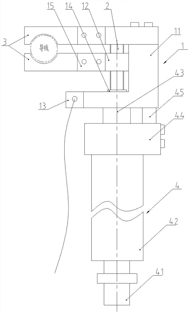
[0027] Embodiment 1, the clamp body of this embodiment is installed horizontally (the clamp body is arranged perpendicular to the wire), and the clamping mold clamps the wire from the upper and lower sides of the wire.

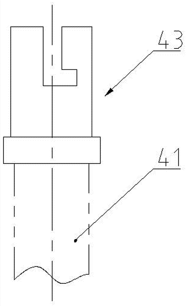
[0028] Such as figure 1 As shown, the multipurpose combined ground clamp assembly provided in this embodiment includes a clamp body 1 , a screw 2 , a clamping mold 3 , and an operating rod 4 .

[0029] Such as figure 1 , figure 2 As shown, the clamp body 1 includes a fixed member 11 and a rectangular movable block 12 . The shape of the fixing member 11 is a C-shape in which the upper side and the lower side are arranged in parallel, and the length of the lower side is greater than that of the upper side. The outer end of the lower side plate has a grounding lead connecting plate 13, and a lead connecting hole is arranged on the grounding lead connecting plate 13.

[0030] The fixing member 11 of this embodiment is spliced ​​by L-shaped members and horizon...

Embodiment 2

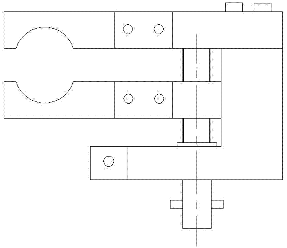
[0038] Embodiment two, such as Figure 4 , Figure 5 As shown, the clamp body of this embodiment is installed longitudinally (the clamp body and the wire are arranged in the same direction), and the clamping mold clamps the wire from the left and right sides of the wire.

[0039] The fixed member of the clamp body in this embodiment has the same structure as that of the first embodiment, but the movable member is a movable beam 12A arranged parallel to the upper side plate of the fixed member.

[0040] Both sides of the upper side plate of the fixed member 11 in the width direction are symmetrically connected with an upper connecting plate 16, and the movable beam 12A includes a middle section 12A1 connected with the screw rod 2 and the fixed member 11 and a lower connecting plate 12A2 symmetrically arranged on both sides of the middle section in the width direction. , the upper connecting plate 16 and the lower connecting plate 12A2 are arranged in parallel, corresponding to...


PUM


Abstract

The invention discloses a multipurpose combined ground clamp module. The multipurpose combined ground clamp module comprises a clamp body, a screw and an operating rod, and a pair of clamping molds directly/indirectly connected with the clamp body; the clamp body comprises a movable component and a C-shaped fixing component; an upper side plate and a lower side plate of the fixing component are parallel; the movable component is connected with an opening of the fixing component; the screw is integrated with the movable component after penetrating the lower side plate of the fixing component; and the operating rod enables the screw to rotate; the movable component can stably move up and down since the screw only rotates but does not generate displacement; the clamp body is connected with a ground lead connection hole; the vertical movement of the movable component enables a function mold directly connected with the clamp body to clamp the upper side and the lower side of the lead and enables the clamping molds indirectly connected with the clamp body to clamp the left side and the right side of the lead; the operating rod and the screw are detachably integrated; the clamp body can be prevented from falling off, and the clamping force of the clamp body is further improved; the clamping molds share the fixing component of the clamp body, and the universality is provided.

Description


Claims


Application Information

Patent Timeline
Owner STATE GRID CORP OF CHINA
Why Eureka
Try Eureka