
Novel bridge device

A bridge and equipment technology, applied in the field of new bridge equipment, can solve problems such as inconvenient maintenance, low compactness, and failure to connect power normally, and achieve the effect of reducing plugging steps and improving plugging efficiency

Inactive Publication Date: 2017-08-29
杭州秀资机械科技有限公司
View PDF0 Cites 12 Cited by
  • Summary
  • Abstract
  • Description
  • Claims
  • Application Information

AI Technical Summary

Problems solved by technology

[0002] In the daily maintenance of some bridges, electrified maintenance equipment is often used. When electrified equipment is used, it needs to be plugged in to provide power. There is a danger of electric shock under human careless touch, and there is a great potential safety hazard. At the same time, some electrified maintenance equipment needs to keep moving during maintenance work. Power is supplied through the existing plug-in method. Although the plug-in is simple, its The tightness is not high, and it will shake with the movement of the electrified maintenance equipment, resulting in loose plug connections and unable to connect normally, which brings great inconvenience to maintenance work and slows down maintenance efficiency

Method used


Image

  • Novel bridge device
  • Novel bridge device
  • Novel bridge device

Examples


Embodiment Construction

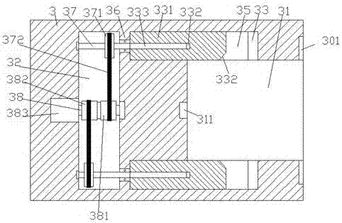
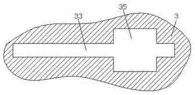
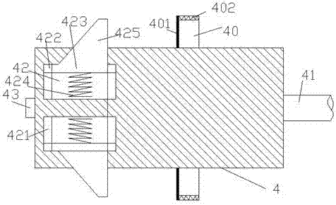
[0022] Such as Figure 1-Figure 7 As shown, a new type of bridge equipment of the present invention includes a base 5, a base 6 installed above the base 5, a push-up block 622, an electrical plug 3 and a plug arranged in the push-up block 622 4. A monitoring probe 7 is provided at the center of the front end of the base 6, and the monitoring probe 7 is used to monitor and shoot illegal vehicles driving on the bridge, thereby improving the orderly passage of vehicles driving on the bridge. The outer surface of the base 5 is fitted with a reflector 8, and the reflector 8 is used for reflection after the light of the vehicle driving at night, so as to facilitate the observation of the driver and prevent the occurrence of collision accidents; the plug-in part 3. There is an inserting groove 31 in the end surface on the right side. Locking grooves 35 are provided in the upper and lower inner walls of the inserting groove 31. The inner walls of the locking groove 35 are provided wit...


PUM


Abstract

The present invention discloses a novel bridge device. The device comprises an engine base, a matrix arranged on the engine base, push-up block, and a plug part and a plug which are arranged in the push-up block, a monitoring probe is arranged at the center of the front end surface of the matrix, reflectors are applied and arranged at the outer surface of the engine base of the lower portion of the matrix, a tight plugging groove is arranged in the end surface of the right side of the plug part, locking grooves are symmetrically arranged at the upper and lower inner walls of the tight plugging groove, sliding grooves extended and arranged towards two sides run through the internal portions of the locking grooves, the plug part at the left side of the tight plugging groove is internally provided with control cavities, baffles are arranged between the control cavities and the extension sections of the left sides of the sliding grooves, a first swivel pin shaft is arranged at the center of the control center, second swivel pin shafts extended and arranged towards two sides are symmetrically arranged in the control cavities at the upper and lower sides of the first swivel pin shaft, the extension sections of the right sides of the second swivel pin shafts run through the baffles and are in rotation matching connection, push blocks are in sliding matching connection in the sliding grooves, spiral thread holes are arranged in the end surfaces of the left sides of the push blocks, and first threaded rods are matchingly connected with the spiral threads in the spiral thread holes. The structure is simple, the operation is convenient, the locking stability is high, and the safety is high.

Description

technical field [0001] The invention relates to the technical field of bridge facilities, in particular to a novel bridge equipment. Background technique [0002] In the daily maintenance of some bridges, electrified maintenance equipment is often used. When electrified equipment is used, it needs to be plugged in to provide power. There is a danger of electric shock under human careless touch, and there is a great potential safety hazard. At the same time, some electrified maintenance equipment needs to keep moving during maintenance work. Power is supplied through the existing plug-in method. Although the plug-in is simple, its The tightness is not high, and it will shake with the electrified maintenance equipment when it moves, resulting in loose plug connections and unable to connect normally, which brings great inconvenience to maintenance work and slows down maintenance efficiency. Contents of the invention [0003] The technical problem to be solved by the present ...

Claims


Application Information

Patent Timeline
Patent Type & Authority Applications(China)
IPC IPC(8): H01R13/629H01R13/627H01R13/44
CPCH01R13/62922H01R13/44H01R13/6273H01R13/62938
Inventor 廖文华
Owner 杭州秀资机械科技有限公司
Learn More