
Electric cable device

A technology for power cables and motors, applied in circuits, electrical components, circuit/collector parts, etc., can solve the problem of inability to clamp various power cables with different thicknesses, reduce the work efficiency of power cable peeling operations, and fail to meet a variety of different Thick and thin power cables need to be clamped and fixed to achieve the effect of convenient handling

Inactive Publication Date: 2017-08-29
姚莉萍
View PDF0 Cites 1 Cited by
  • Summary
  • Abstract
  • Description
  • Claims
  • Application Information

AI Technical Summary

Problems solved by technology

[0002] Power cables are widely used in the power industry. In the process of use, the head of the power cable needs to be stripped to facilitate power connection. However, there are many types of power cables, and each type of power cable has different thicknesses. It is not the same. During the stripping operation, the general clamping device cannot clamp a variety of power cables with different thicknesses, which leads to the cost of the power cable stripping operation and reduces the work efficiency of the power cable stripping operation. Therefore, The existing general clamping devices cannot meet the clamping and fixing requirements for various power cables of different thicknesses

Method used


Image

  • Electric cable device
  • Electric cable device
  • Electric cable device

Examples


Embodiment Construction

[0019] The preferred embodiments of the present invention will be described in detail below in conjunction with the accompanying drawings, so that the advantages and features of the present invention can be more easily understood by those skilled in the art, so as to define the protection scope of the present invention more clearly.

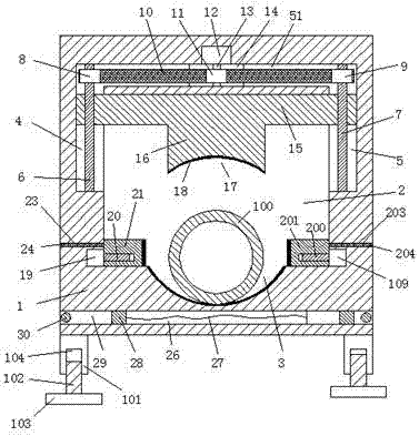
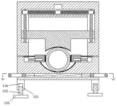
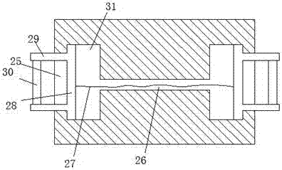
[0020] refer to Figure 1-4 The power cable device shown includes a body 1 and an inner cavity 2 arranged in the body 1 and penetrated front and rear. Standing feet 101 are fixedly installed on the four corners of the bottom of the body 1, and each of the standing feet The bottom of 101 is provided with an adjustment slot 104 with the opening facing downwards. The screw matching thread in the adjustment slot 104 is connected with a screw matching foot 102. The bottom of the screw matching foot 102 is fixedly equipped with a balance foot 103. The cooperation of the adjustment groove 104 can adjust the height of the balance foot 113, which is conve...


PUM


Abstract

The invention discloses an electric cable device, which comprises a main body and an inner cavity arranged in the main body and penetrated through from the front part to the back part; vertical stands are fixedly mounted on four corners of the bottom part of the main body, and the bottom part of every vertical stand is provided with an adjusting slot with a downward opening; a matching thread in the adjusting slot is in fit connection with a screw foot, and the bottom part of the screw foot is fixedly equipped with a balance foot; a first concaved arc slot is arranged in the side wall of the bottom side of the inner cavity, a left sliding groove and a right sliding groove are equally arranged on the top part of a left side wall and the top part of a right side wall of the inner cavity respectively; a combining groove for connecting the left sliding groove with the right sliding groove is arranged in the top side wall of the inner cavity. The electric cable device is reasonable in structure, simple in operation, and convenient to move; the cable clamping is safe and stable without offset, so that the subsequent head peeling work of the cable can be carried out conveniently; meanwhile, the electric cable device can clamp cables with different thicknesses, the clamping and fixing cost of the cable is greatly reduced; therefore, the electric cable device is suitable for popularize and use.

Description

technical field [0001] The invention relates to the technical field of power cables, in particular to a power cable device. Background technique [0002] Power cables are widely used in the power industry. In the process of use, the head of the power cable needs to be stripped to facilitate power connection. However, there are many types of power cables, and each type of power cable has different thicknesses. It is not the same. During the stripping operation, the general clamping device cannot clamp a variety of power cables with different thicknesses, which leads to the cost of the power cable stripping operation and reduces the work efficiency of the power cable stripping operation. Therefore, Existing general clamping devices cannot meet the clamping and fixing requirements for power cables of various thicknesses. Contents of the invention [0003] The technical problem to be solved by the present invention is to provide a power cable device, which can solve the above...

Claims


Application Information

Patent Timeline
Patent Type & Authority Applications(China)
IPC IPC(8): H01R43/28
CPCH01R43/28
Inventor 姚莉萍
Owner 姚莉萍
Learn More