High-speed linear electromagnetic brake

A linear electromagnetic and brake technology, applied in the direction of electric motor/converter plugs, electric components, AC motor control, etc., can solve the problem that the characteristics of braking force cannot take into account high speed and low speed, the magnetic field size of permanent magnets cannot be adjusted at will, and the dynamic performance is poor, etc. problems, to achieve the effect of shortening the braking distance, improving system reliability and reducing costs

Active Publication Date: 2017-08-29
HARBIN INST OF TECH
View PDF4 Cites 4 Cited by
  • Summary
  • Abstract
  • Description
  • Claims
  • Application Information

AI Technical Summary

Problems solved by technology

[0004] The present invention aims to solve the temperature rise caused by the existing electromagnetic eddy current braking, and the permanent magnetic eddy current is used for braking. Once the permanent magnet in the permanent magnetic edd

Method used


Image

  • High-speed linear electromagnetic brake
  • High-speed linear electromagnetic brake
  • High-speed linear electromagnetic brake

Examples


specific Embodiment approach 1

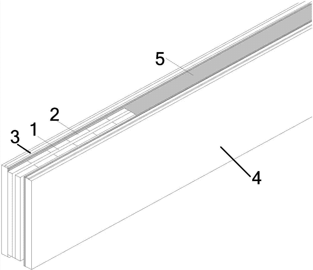
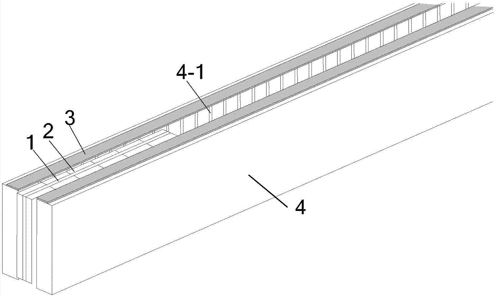
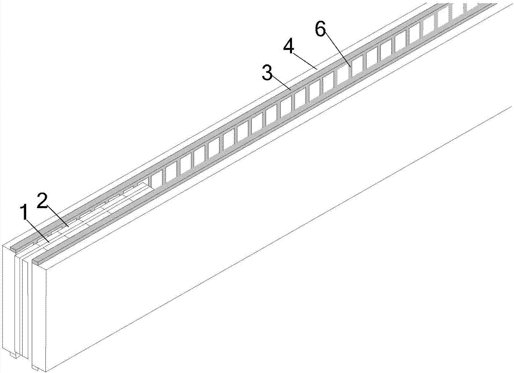
[0025] Specific implementation mode one: refer to figure 1 Describe this embodiment in detail. The high-speed linear electromagnetic brake described in this embodiment includes a double-sided primary and a variable structure secondary. The primary is a short primary, and the variable structure secondary is a long secondary.

[0026] primary motion, secondary static during runtime,

[0027] The primary is composed of a primary substrate 1 and a primary permanent magnet 2; the primary substrate 1 is flat, and on the side of the primary substrate 1 facing the air gap, strip-shaped primary permanent magnets 2N and S are arranged alternately along the direction of motion;

[0028] The structure of the variable structure secondary gradually changes from the high-speed section to the low-speed section to obtain high braking force density.

Embodiment 1

[0030] Such as figure 1 As shown, the variable structure secondary includes a magnetic conductor plate, a high-conductivity non-magnetic side strip and a high-conductivity non-magnetic metal sheet. The high-conductivity non-magnetic metal sheet is pasted and fixed on the air gap side of the magnetic conductor plate. Two high-conductivity The high-rate non-magnetic edge strips are closely combined on the left and right sides of the magnetic conductor plate and the high-conductivity non-magnetic metal sheet; from the medium speed section to the low-speed section, the thickness of the high-conductivity non-magnetic metal sheet The lateral width of the thin plate is greater than or equal to the lateral width of the primary permanent magnet.

Embodiment 2

[0032] Such as figure 2 As shown, the main difference between this embodiment and Embodiment 1 is that in the low-speed section, the variable structure secondary is composed of a magnetic conductor plate and a high-conductivity non-magnetic side strip, and a narrow groove is opened in the transverse direction on the air gap side of the magnetic conductor plate , The lateral ends of the magnetic conductor plate are closely combined with the high-conductivity non-magnetic side strips.


PUM


Abstract

A high-speed linear electromagnetic brake relates to the field of a motor and aims to solve the problems that the size of a magnetic field generated by a permanent magnet cannot be randomly adjusted, the dynamic property is poor and the brake characteristic cannot be compatible with high speed and low speed once the permanent magnet in permanent-magnet eddy brake is installed due to the adoption of permanent-magnet eddy to brake and temperature rising caused by the adoption of electromagnetic eddy to brake. The high-speed linear electromagnetic brake comprises a bilateral primary and a variable-structure secondary, wherein the primary is a short primary, the variable-structure secondary is a long secondary, the primary moves and the secondary is fixed during running, the primary comprises a primary substrate and primary permanent magnets, the primary substrate is in a flat shape, the elongate permanent magnets are alternatively arranged along a motion direction in an N-S way at a gap-facing side of the primary substrate, and the structure of the variable-structure secondary is gradually changed from a high-speed segment to a low-speed segment to acquire high brake density.

Description

technical field [0001] The invention relates to a high-speed linear electromagnetic brake and belongs to the field of motors. Background technique [0002] Permanent magnet eddy current braking is a new type of braking technology developed in the 1990s. It uses the strong eddy current generated by the conductor moving in the permanent magnet array and the interaction between the eddy current magnetic field and the permanent magnet magnetic field for braking. There is no friction and no contact during the braking process, and the external environment has no effect on the braking effect. Permanent magnet braking requires no external energy, no noise, no vibration, no pollution, weather resistance, and no wear during braking. It is a green, environmentally friendly, and highly reliable braking technology. It has gradually become the field of braking technology. New directions for research development. [0003] Compared with electromagnetic eddy current braking, the main advan...

Claims


Application Information

Patent Timeline
IPC IPC(8): H02K41/025H02K11/00H02P25/06H02P3/20
CPCH02K11/00H02K41/025H02P3/20H02P25/06
Inventor 寇宝泉陈雯金银锡张赫张鲁
Owner HARBIN INST OF TECH
Why Eureka
Try Eureka