Electromagnetic braking linear motor system and its control method
A technology of linear motor and electromagnetic brake, which is applied in the direction of motor generator control, AC motor control, control system, etc., can solve the problems of rail temperature rise, etc., to reduce the length of the end, reduce the volume and weight, and reduce the output Effect of Current and Loss
- Summary
- Abstract
- Description
- Claims
- Application Information
AI Technical Summary
Problems solved by technology
Method used
Image
Examples
specific Embodiment approach 1
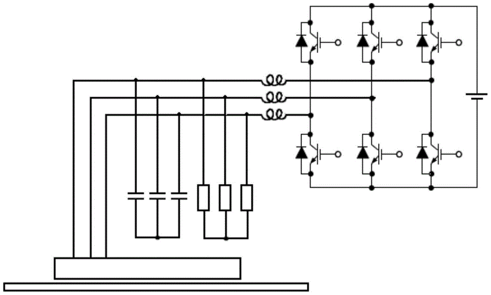
[0024] Specific implementation mode one: see figure 2 This embodiment will be described. The electromagnetic braking linear motor system described in this embodiment includes a linear motor and an inverter. The system also includes a multi-phase exciting capacitor bank and a plurality of inductors. The linear motor is a flat linear induction motor. The induction motor includes a primary and a secondary, the primary includes a primary iron core and a primary winding, the side of the primary iron core facing the air gap has a slot perpendicular to the relative movement direction of the primary and the secondary, and the primary winding is embedded in the slot, the The primary winding is an annular multi-phase symmetrical winding, the output end of the annular multi-phase symmetrical winding is connected to the inverter, and a set of multi-phase exciting capacitor banks is connected in parallel to the output end of the annular multi-phase symmetrical winding; An inductor is con...
specific Embodiment approach 2
[0028] Specific implementation mode two: see figure 2 This embodiment will be described. The difference between this embodiment and the electromagnetic braking linear motor system described in Embodiment 1 is that this embodiment adds a plurality of inductors, and an inductor is connected in series between the output end of each phase winding in the primary winding and the inverter.
[0029] see figure 2 As shown, it is a structural schematic diagram of an electromagnetic braking linear motor system described in this embodiment. This structure is composed of a linear motor, an exciting capacitor bank, an energy absorbing resistor bank and an inverter. The linear motor includes a primary and Secondary, the primary is mainly composed of a primary iron core and a primary winding; the primary iron core is in the shape of a flat plate, and slots are made perpendicular to the direction of motion on the side of the primary iron core facing the air gap, and a set of annular multi-p...
specific Embodiment approach 3
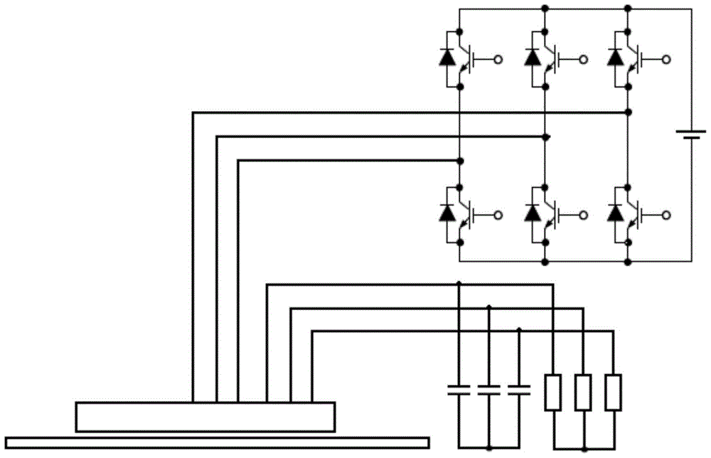
[0031] Specific implementation mode three: see figure 1This embodiment will be described. The electromagnetic braking linear motor system described in this embodiment includes a linear motor and an inverter. The system also includes a multi-phase excitation capacitor bank. The linear motor is a flat linear induction motor, and the linear induction motor includes a primary and secondary, the primary includes a primary core and a primary winding, the primary winding is composed of two sets of ring-shaped multi-phase symmetrical windings, and the primary core is slotted on the side facing the air gap perpendicular to the relative movement direction of the primary and secondary A primary winding is embedded in the slot, one set of annular multi-phase symmetrical windings in the primary winding is connected to the multi-phase excitation capacitor bank, and the other set of annular multi-phase symmetrical windings is connected to the inverter.
[0032] The main difference between t...
PUM
 Abstract
Description
Claims
Application Information
 - R&D
- Intellectual Property
- Life Sciences
- Materials
- Tech Scout
- Unparalleled Data Quality
- Higher Quality Content
- 60% Fewer Hallucinations
Browse by: Latest US Patents, China's latest patents, Technical Efficacy Thesaurus, Application Domain, Technology Topic, Popular Technical Reports.
© 2025 PatSnap. All rights reserved.Legal|Privacy policy|Modern Slavery Act Transparency Statement|Sitemap|About US| Contact US: help@patsnap.com


