Test platform for rotor power system of small multi-rotor unmanned aerial vehicle

A multi-rotor unmanned and power system technology, which is applied in the test platform field of small multi-rotor UAV rotor power system, can solve the problems of small application range, lack of diversity in installation, and inability to test the force of the hub, etc., to achieve Smooth friction, simple structure, convenient installation and disassembly

Pending Publication Date: 2017-09-01
ANHUI UNIVERSITY OF TECHNOLOGY AND SCIENCE
View PDF1 Cites 12 Cited by
  • Summary
  • Abstract
  • Description
  • Claims
  • Application Information

AI Technical Summary

Problems solved by technology

[0004] The Chinese patent publication number is CN105947233A, which discloses a multi-rotor power testing device and method, which can test the power performance and power supply performance of a multi-rotor UAV, but can only measure the pulling force and torque in a single direction, and cannot test the hub Magnitude of the force
Due to the low efficiency and accuracy of the airflow test of the propeller, the installation does not have diversity, and the application range is small

Method used


Image

  • Test platform for rotor power system of small multi-rotor unmanned aerial vehicle
  • Test platform for rotor power system of small multi-rotor unmanned aerial vehicle
  • Test platform for rotor power system of small multi-rotor unmanned aerial vehicle

Examples


Embodiment Construction

[0030] In order to make the technical means, creative features, goals and effects achieved by the present invention easy to understand, the present invention will be further elaborated below.

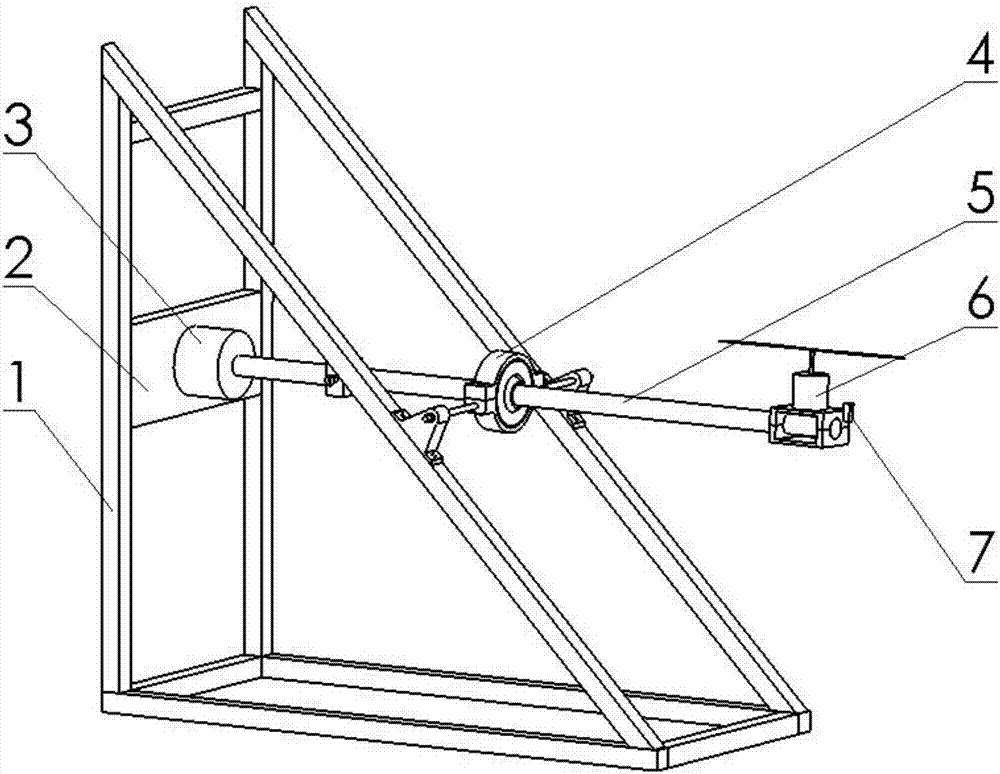
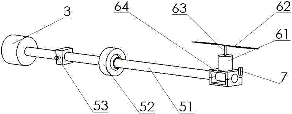
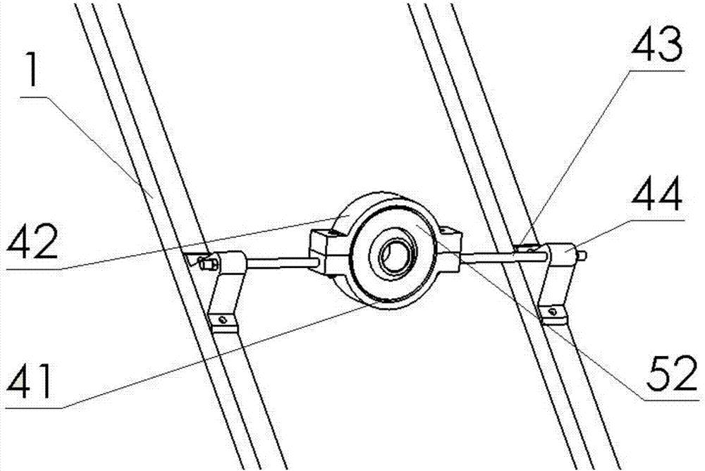
[0031] Such as Figure 1 to Figure 4 As shown, a test platform of a small multi-rotor UAV rotor power system includes a triangular support 1, the middle part of the triangular support 1 is equipped with a support plate 2 perpendicular to the ground, and the middle part of the support plate 2 is equipped with a three-dimensional Force sensor 3, support unit 4 is also installed in the middle part of described triangular support 1, and the balance lever unit 5 that one end links to each other with three-dimensional force sensor 3 is installed on described support unit 4, and the other end of described balance lever unit 5 is installed useful To fix the mounting bracket 64 of the motor-rotor unit 6, the photoelectric sensor 7 for testing the rotating speed of the rotor is installed near the...


PUM


Abstract

The invention relates to a test platform for a rotor power system of a small multi-rotor UAV, which includes a triangular support, a support plate is installed in the middle of the triangular support, a three-dimensional force sensor is installed in the middle of the support plate, and a support unit is also installed in the middle of the triangular support , a balance lever unit with one end connected to the three-dimensional force sensor is installed on the support unit, the other end of the balance lever unit is installed with a mounting bracket for fixing the motor-rotor unit, and a test rotor is installed on the mounting bracket near the position of the motor-rotor unit The photoelectric sensor of the rotational speed, the three-dimensional force sensor, and the photoelectric sensor are connected with a control system for testing the motor-rotor unit. The invention is convenient for installation and disassembly, and can simultaneously measure the rotating speed, thrust and hub force of the rotor, and at the same time, the length of the force arm can be changed by moving the counterweight on the lever shaft, so that the combination of different motors and rotors can be replaced. The purpose of the experiment.

Description

technical field [0001] The invention relates to the technical field of multi-rotor UAV testing, in particular to a test platform for a small multi-rotor UAV rotor power system. Background technique [0002] Multi-rotor drones are a type of rotor drones that can take off and land vertically. Because it does not need a long take-off and landing runway, it can hover in the air and fly in all directions, and it has the advantages of simple structure, easy maintenance and manipulation, and low cost of use. It is widely used in various military and civilian fields. . The power system of this type of small UAV consists of an onboard power battery, a speed control unit, a DC brushless servo motor and a propeller. Under the control of the control unit, the battery-powered DC motor drives the propeller to rotate, providing the required thrust for the drone to drive it to fly in the air. Therefore, the dynamic performance of the power system has a crucial impact on the overall perfo...

Claims


Application Information

Patent Timeline
Patent Type & Authority Applications(China)
IPC IPC(8): B64F5/60
CPCB64F5/60
Inventor 刘明黄强王海曹会彬潘宏青张强曹平国许德章
Owner ANHUI UNIVERSITY OF TECHNOLOGY AND SCIENCE
Why Eureka
Try Eureka