
Clutch assembly capable of automatically compensating wear

An automatic compensation and clutch technology, applied in the field of vehicle engineering, can solve the problem of no automatic compensation for wear of the driven disc, and achieve the effect of increasing the design service life and simple structure

Active Publication Date: 2017-09-01
日照普拉沃夫机械制造有限公司
View PDF7 Cites 2 Cited by
  • Summary
  • Abstract
  • Description
  • Claims
  • Application Information

AI Technical Summary

Problems solved by technology

At present, most clutches do not have the function of automatically compensating for the wear of the driven disc.

Method used


Image

  • Clutch assembly capable of automatically compensating wear
  • Clutch assembly capable of automatically compensating wear
  • Clutch assembly capable of automatically compensating wear

Examples


Embodiment Construction

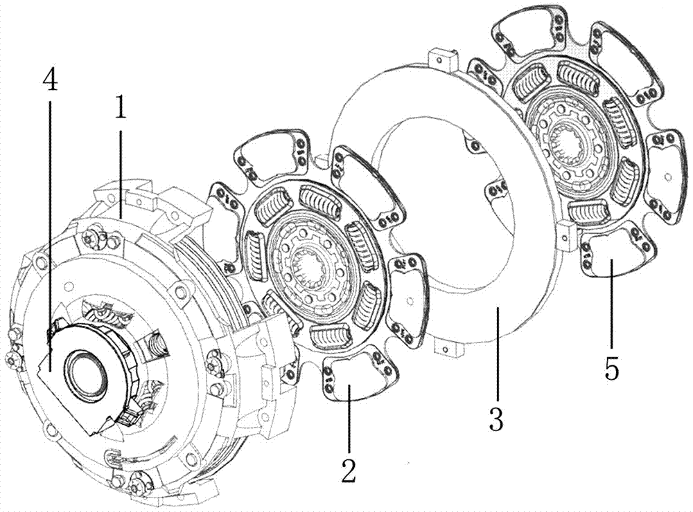
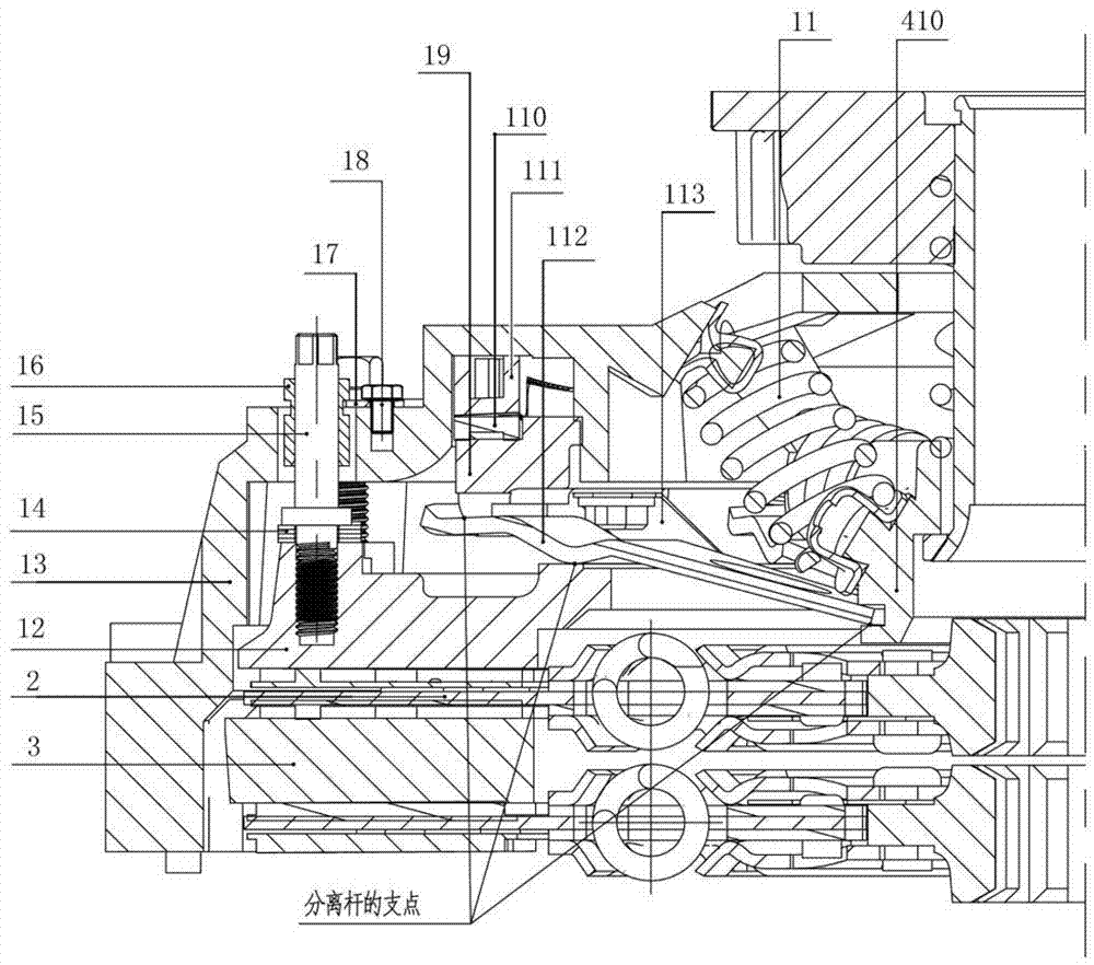
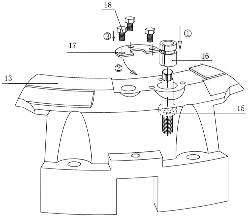
[0033] The present invention will be described in detail below in conjunction with accompanying drawing: figure 1 As shown, a clutch assembly that can automatically compensate for wear includes a cover assembly 1 with a sensing device, a driven disc inner plate assembly 2, an intermediate pressure plate 3, a release bearing assembly 4 and a driven disc outer plate Assembly 5, the cover assembly 1 with sensing device and the intermediate pressure plate 3 are connected through the limit groove on the gland 13, and the inner plate assembly 2 of the driven disc is pressed between the cover assembly 1 with sensing device and Between the middle pressure plate 3, the driven disc outer plate assembly 5 is located outside the middle pressure plate 3; the engine matched with the clutch assembly that can automatically compensate for wear is provided with a flywheel, and the driven plate outer plate assembly 5 is Press between the flywheel and the middle pressure plate 3 .

[0034] As sh...


PUM


Abstract

The invention discloses a clutch assembly capable of automatically compensating wear. The clutch assembly comprises a cover assembly with an induction device, a driven disc inner sheet assembly, a middle pressing disc, a release bearing assembly and a driven disc outer sheet assembly; the cover assembly with the induction device is connected with the middle pressing disc through limitation grooves in a pressing cover; the driven disc inner sheet assembly is pressed between the cover assembly with the induction device and the middle pressing disc; and the driven disc outer sheet assembly is located on the outer side of the middle pressing disc and is pressed between the middle pressing disc and an engine flywheel. The clutch assembly capable of automatically compensating the wear has the characteristics that the wear of a friction component can be inducted by the clutch assembly, so that relative sliding of adjustment rings in the cover assembly is caused and the worn part of the friction component is compensated; the clutch assembly is simple in structure; within the range of the life of a friction sheet, stable performance parameters of the pressing disc can be kept; and the design service life of a clutch is prolonged.

Description

technical field [0001] The invention relates to a clutch assembly capable of automatically compensating wear and belongs to the field of vehicle engineering. Background technique [0002] The current automobile clutch is basically defined as a loss part of the automobile. With the wear of the friction parts during use, the performance of the clutch cover assembly is also changing. [0003] The clutch assembly consists of two parts: the driven plate assembly and the pressure plate assembly. The friction plate of the driven plate and the pressure plate become thinner due to wear during use, and the amount of wear is generally about 3mm. During this period, the pressure plate The working position of the diaphragm spring (or helical spring) of the elastic element on the disk assembly will change with the thickness of the driven disk, and the height of the separation finger will change, so that the pressing force will decrease and the separation force will increase. At present, ...

Claims


Application Information

Patent Timeline
Patent Type & Authority Applications(China)
IPC IPC(8): F16D13/70F16D13/60F16D13/58
CPCF16D13/58F16D13/60F16D13/70
Inventor 张建平
Owner 日照普拉沃夫机械制造有限公司
Learn More