Flexible pressure sensor with interlaced microstructure and manufacturing method thereof

A pressure sensor and manufacturing method technology, applied in the direction of instruments, measuring force, measuring devices, etc., can solve the problems of insufficient measuring range, sensitivity and response time, uneven distribution of carbon nanotubes, difficult control of spraying process, etc., and achieve improved linearity. Measurement range and sensitivity, stable and reliable production, and the effect of improving performance parameters

Inactive Publication Date: 2019-03-19
SHENZHEN INST OF ADVANCED TECH CHINESE ACAD OF SCI
View PDF4 Cites 15 Cited by
  • Summary
  • Abstract
  • Description
  • Claims
  • Application Information

AI Technical Summary

Problems solved by technology

[0009] 1. As the diameter of the cylinder increases, the linear range of the flexible pressure sensor based on the cylindrical structure array becomes smaller, which limits its wide range of applications.
[0010] 2. When the flexible sensor combined with the dielectric material is sprayed with gold nanowires, its sensitivity becomes very low and the response time increases when a pressure greater than 500Pa is applied, which is only suitable for measuring smaller pressures
[0011] 3. Although the flexible sensor based on the porous structure has good stability and high transparency, its sensitivity is relatively low, only 0.63 / kPa, which is destined to be not widely used
[0012] 4. Based on the flexible pressure sensor of sprayed single-walled carbon nanotubes, the spraying process is difficult to control, and it is prone to uneven distribution of carbon nanotubes
[0013] In summary, the flexible pressure sensor in the prior art has insufficient measurement range, sensitivity and response time, and the measurement effect is not good

Method used


Image

  • Flexible pressure sensor with interlaced microstructure and manufacturing method thereof
  • Flexible pressure sensor with interlaced microstructure and manufacturing method thereof
  • Flexible pressure sensor with interlaced microstructure and manufacturing method thereof

Examples


Embodiment Construction

[0046] In order to make the object, technical solution and advantages of the present invention clearer, the present invention will be further described in detail below in conjunction with the accompanying drawings and embodiments. It should be understood that the specific embodiments described here are only used to explain the present invention, not to limit the present invention.

[0047] It should be noted that the terms "setting" and "connecting" should be understood in a broad sense, for example, they can be directly set and connected, or indirectly set and connected through a central component or a central structure.

[0048] In addition, if there are "longitudinal", "transverse", "length", "width", "thickness", "upper", "lower", "front", "rear", "left", " Terms such as "right", "vertical", "horizontal", "top", "bottom", "inner", "outer", etc. indicate the orientation or positional relationship, which are based on the orientation or positional relationship shown in the dr...


PUM

PropertyMeasurementUnit
tensile strengthaaaaaaaaaa
elastic modulusaaaaaaaaaa
tensile strengthaaaaaaaaaa

Abstract

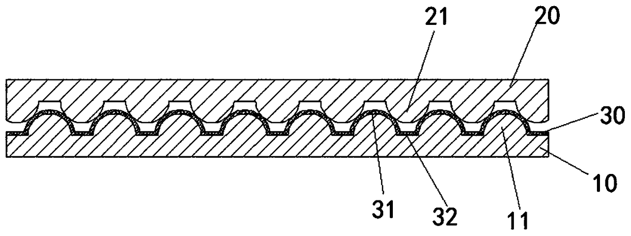
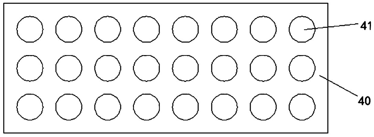
The invention is applicable to the technical field of sensor fabrication and packaging, and discloses a flexible pressure sensor with an interlaced microstructure and a manufacturing method thereof. The flexible pressure sensor consists of first and second flexible substrates, and a carbon nanotube film is arranged between the first and second flexible substrates. One sides of the first and secondflexible substrates are provided with several spherical-crown-shaped staggered first and second protrusions respectively, and the carbon nanotube film is attached to the surface, with the first protrusions, of the first flexible substrate. The manufacturing method is used for manufacturing the flexible pressure sensor. According to the flexible pressure sensor with the interlaced microstructure and the manufacturing method thereof, a staggered hemispherical internal structure is adopted, through the combination of the high conductivity of carbon nanotubes, the linear measurement range and sensitivity of the sensor are improved, the stability, the precision, the accuracy and the reliability are high, and the response time is short.

Description

technical field [0001] The invention belongs to the technical field of sensor manufacturing and packaging, and in particular relates to a flexible pressure sensor with an interlaced microstructure and a manufacturing method thereof. Background technique [0002] In recent years, with the rapid development of economy and society, people's quality of life has been greatly improved, and people's attention to health issues has been promoted. The skin senses complex signals such as temperature, pressure, deformation or texture of the outside world, and through the electronic skin, the external stimulation is converted into a transmissible electrical signal to output or even convey the commands of the brain. Traditional sensors are mostly based on metal and semiconductor materials, which are poor in portability, flexibility and wearable properties. Due to the good biocompatibility of flexible sensors, as well as a series of advantages such as wearability, real-time monitoring, an...

Claims


Application Information

Patent Timeline
Patent Type & Authority Applications(China)
IPC IPC(8): G01L1/20
CPCG01L1/20
Inventor 李晖谢振文王磊
Owner SHENZHEN INST OF ADVANCED TECH CHINESE ACAD OF SCI
Why Eureka
Try Eureka