Modular connector

a module connector and connector technology, applied in the field of connectors, can solve the problems of incorrect coupling prevention, securing/insulating coupling contact members, coupling device connections, etc., and achieve the effects of improving relative localisation and mounting of parts, facilitating determining proper alignment, and facilitating defining proper alignmen

Active Publication Date: 2012-07-03
FCI ASIA PTE LTD
View PDF9 Cites 30 Cited by
  • Summary
  • Abstract
  • Description
  • Claims
  • Application Information

AI Technical Summary

Benefits of technology

[0007]Such a connector may be assembled efficiently. The profile having an asymmetric cross-section provides an asymmetric acceptance for manufacturing tolerances of the mounting structure and receiving structures in an assembled state, and therefore improves the localisation and mounting accuracy of the parts relative to each other.
[0022]Such an electrical connector may be manufactured relatively efficiently and reliably and be assembled relatively efficiently. The perpendicular surfaces enable a relatively reliable alignment of the module and the housing and therewith provide a relatively good localisation and mounting accuracy.

Problems solved by technology

However, with the ever increasing signalling speed required by present-day systems the signals transmitted over a contact terminal become more and more sensitive to cross talk with neighbouring contact terminals, also with contacts in adjacent terminal modules or terminal modules separated by one or more spacer modules or other terminal modules.

Method used


Image

  • Modular connector
  • Modular connector
  • Modular connector

Examples


Embodiment Construction

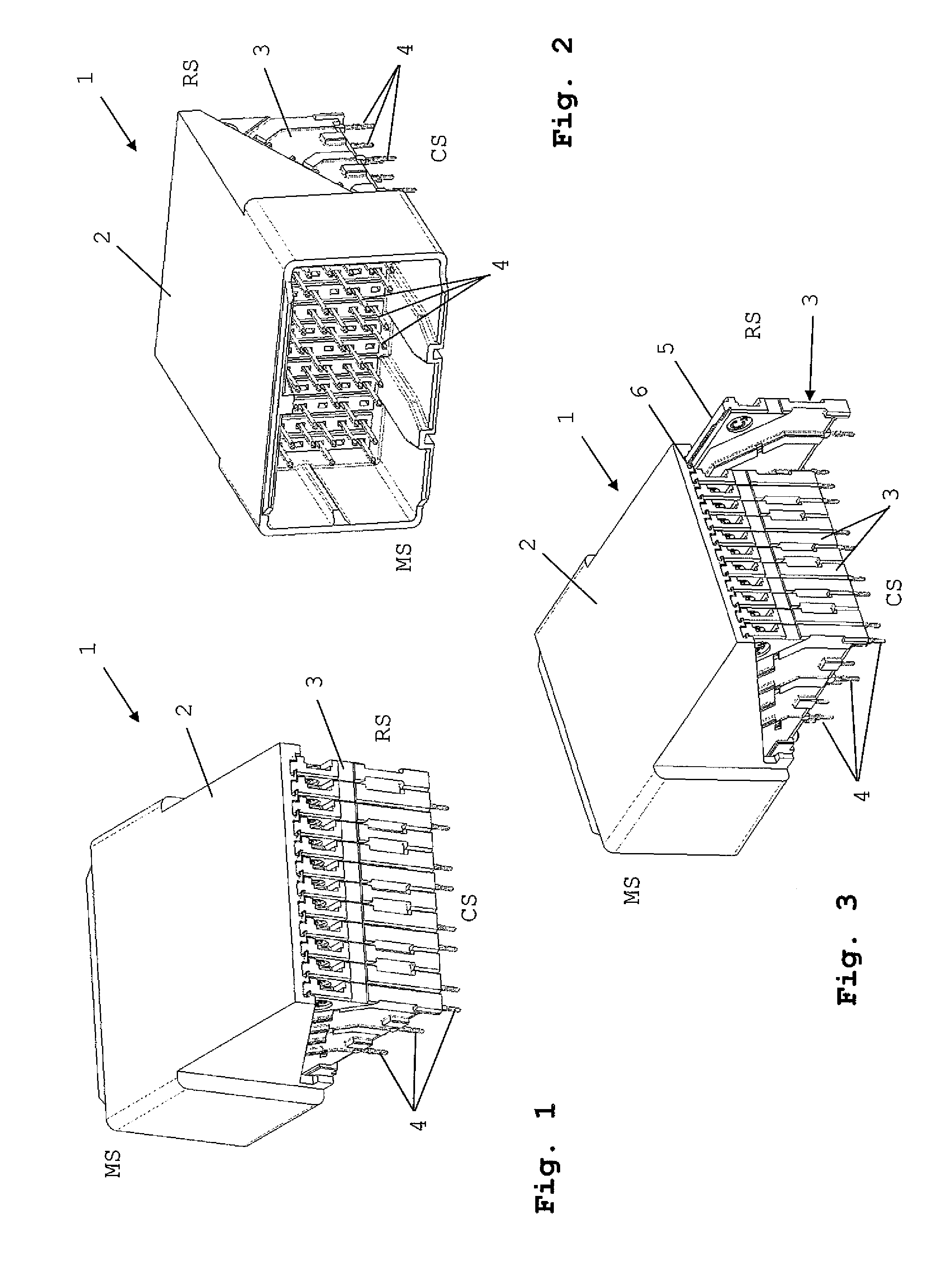
[0031]FIGS. 1-3 show an electrical connector 1, here in the form of a right-angle board connector, having a front or mating side MS for mating with a counterconnector, a rear side RS and a contact side CS for contact with a printed circuit board (not shown). It should be noted that the connector 1 according to the invention may equally well be formed as a straight connector, a board-to-board mezzanine connector etc.

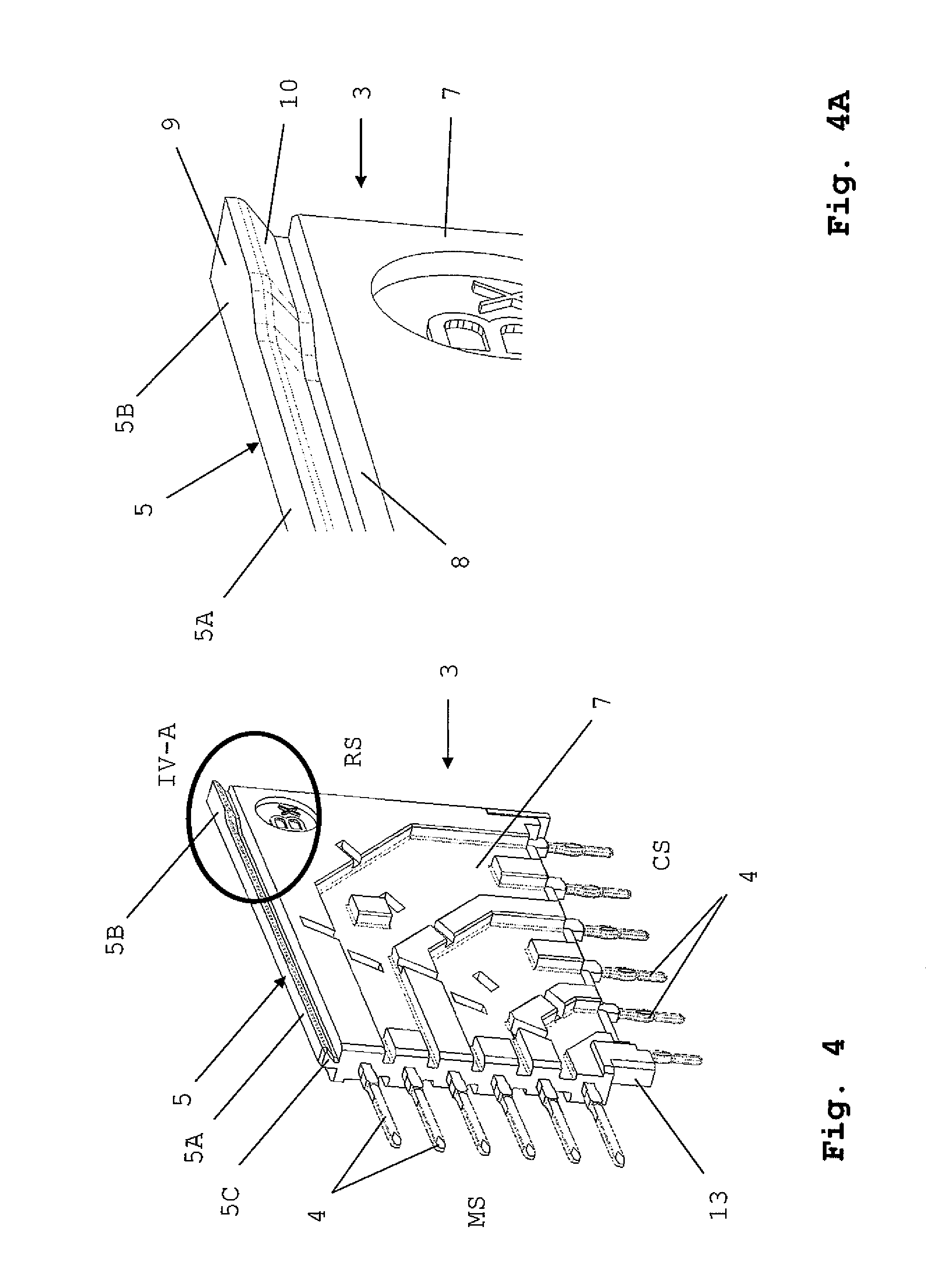
[0032]The connector 1 comprises a housing 2 and a plurality of modules 3. The modules 3 may be identical or different and may comprise any suitable number of contact terminals or no terminals at all, being merely spacer modules. In the embodiment shown, all modules comprise contact terminals 4. Here, the contact terminals 4 extend from the mating side MS of the connector to the contact side CS.

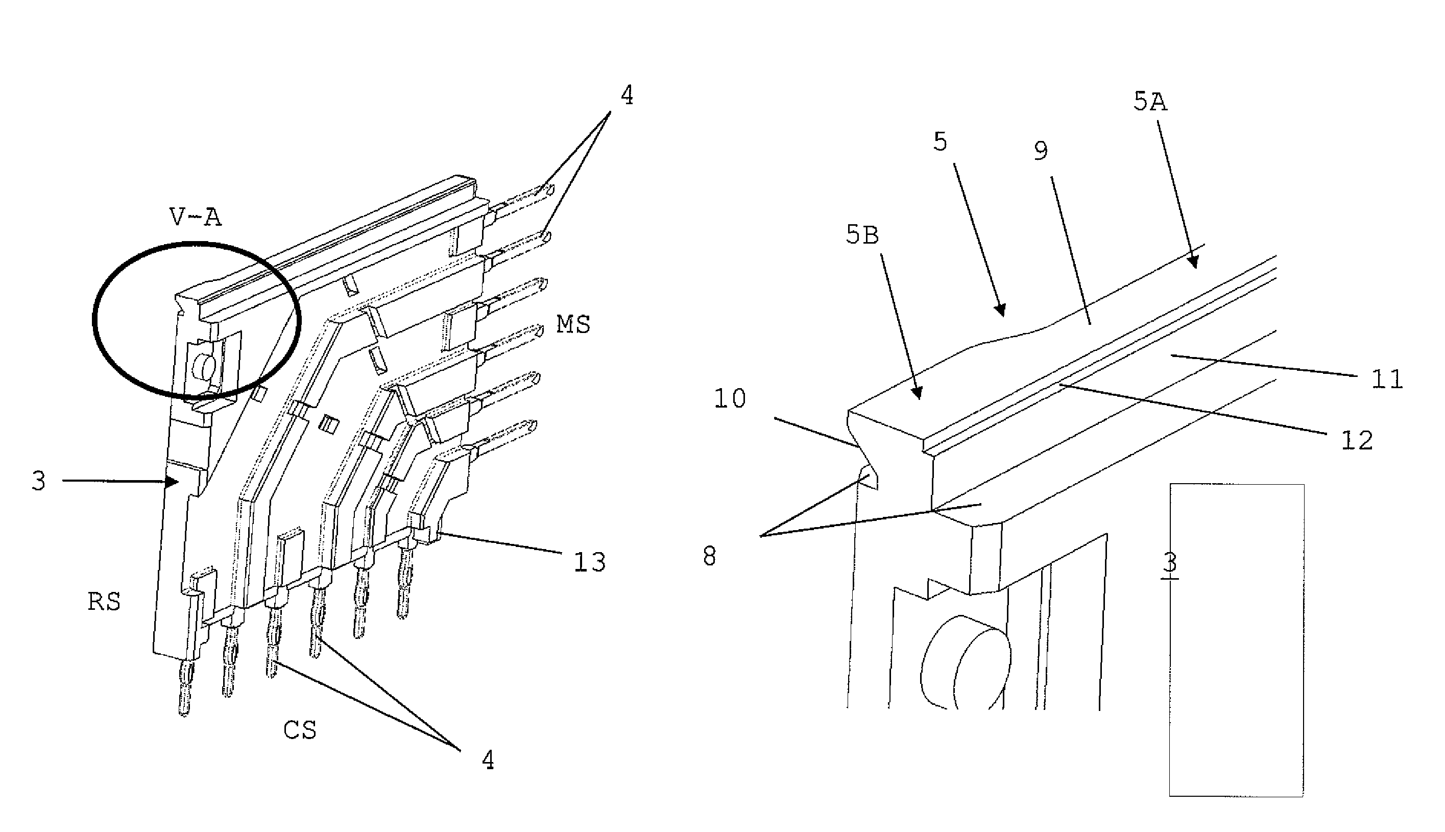
[0033]The modules 3 are mounted into the housing 2 from the rear side RS. The modules 3 are attached to the housing 2 by means of rib 5, fitting into a corresponding slot 6 in the h...


PUM


Abstract

An electrical connector includes at least two parts: a housing having a mating side (MS) and a rear side (RS) and a terminal module having a mating side and a rear side. One part includes a mounting structure and the other part includes a corresponding receiving structure for receiving the mounting structure of the other part. The mounting structure extends in a direction from the mating side to the rear side of the part and includes a cross-section perpendicular to that direction, which cross-section has an asymmetric profile.

Description

FIELD OF THE DISCLOSURE[0001]The present invention relates to the field of connectors. In particular, the present invention relates to the field of modular connectors. More in particular, the present invention relates to the field of electrical connectors for transmitting high speed signals.BACKGROUND OF THE DISCLOSURE[0002]In the art, various modular connectors are known wherein modules, such as terminal modules, insulating modules and / or spacer modules, are arranged in a housing such as a header or a housing. Different connectors may be formed by assembling different numbers and / or types of modules into the the housing. The modules may be arranged in a side-by-side relationship.[0003]Such connectors, e.g. known from U.S. Pat. No. 6,083,047, are very well suited for transmitting high speed signals. The connector according to U.S. Pat. No. 6,083,047 may be assembled relatively efficiently by virtue of the fact that the modules are provided with a locating and mounting rib having a d...

Claims


Application Information

Patent Timeline
Patent Type & Authority Patents(United States)
IPC IPC(8): H01R13/648
CPCH01R12/712H01R13/514H01R13/6587
Inventor DROESBEKE, GERT
Owner FCI ASIA PTE LTD
Why Eureka
Try Eureka