
Device for cutting packing bag, device for producing packing bag and method for producing packing bag

a cutting device and packing bag technology, applied in the field of cutting devices, devices for producing packing bags and producing packing bags, can solve the problems of deteriorating operation efficiency, inability to completely remove chips, and expensive machines to be introduced, so as to reduce costs

Inactive Publication Date: 2010-08-19
IDEMITSU UNITECH CO LTD
View PDF12 Cites 24 Cited by
  • Summary
  • Abstract
  • Description
  • Claims
  • Application Information

AI Technical Summary

Benefits of technology

[0011]Accordingly, an object of the present invention is to provide: a cutter for a packaging bag that requires low equipment cost, exhibits a favorable cutting performance and reliably manufactures a packaging bag having a predetermined shape; a manufacturing device of the packaging bag; and a manufacturing method of the packaging bag.Means for Solving the Problems
[0036]According to the above aspect of the invention, for instance, three sides of the base film are sealed by the sealer to form the partition, followed by supplying the base film to the female blade and advancing / retracting the male blade along the fitting portion of the female blade. Thus, the manufacturing method, in which the base film is cut by the above cutter, can provide the same advantages as the above. Particularly, a packaging bag of high quality in which no protrusion is formed at a cut edge is obtained and cost can be reduced by introducing an inexpensive cutter.

Problems solved by technology

However, when cutting lines are respectively cut off by two blades, cut-off chips have cling to the blades with static, thereby deteriorating operation efficiency.
Though the chips are to be removed by air treatment, the chips cannot be removed completely.
In addition, a very expensive machine needs to be introduced as an equipment to cut the two straight lines individually, which costs considerably.
Accordingly, the receiving portion needs regular exchange, which consumes time and invites cost.
Moreover, cutting with a thin blade is likely to cause poor cutting.

Method used


Image

  • Device for cutting packing bag, device for producing packing bag and method for producing packing bag
  • Device for cutting packing bag, device for producing packing bag and method for producing packing bag
  • Device for cutting packing bag, device for producing packing bag and method for producing packing bag

Examples


Embodiment Construction

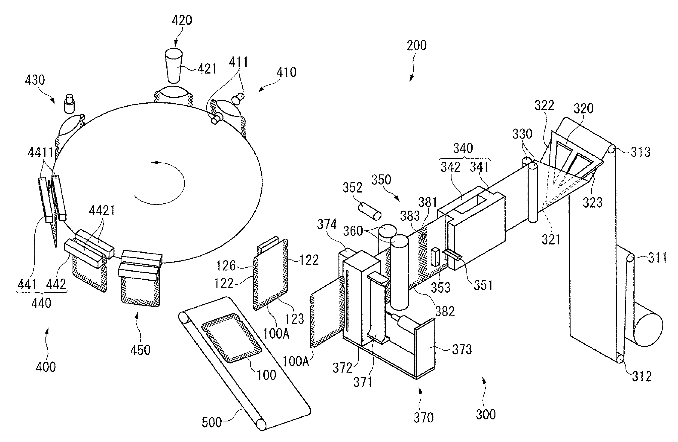
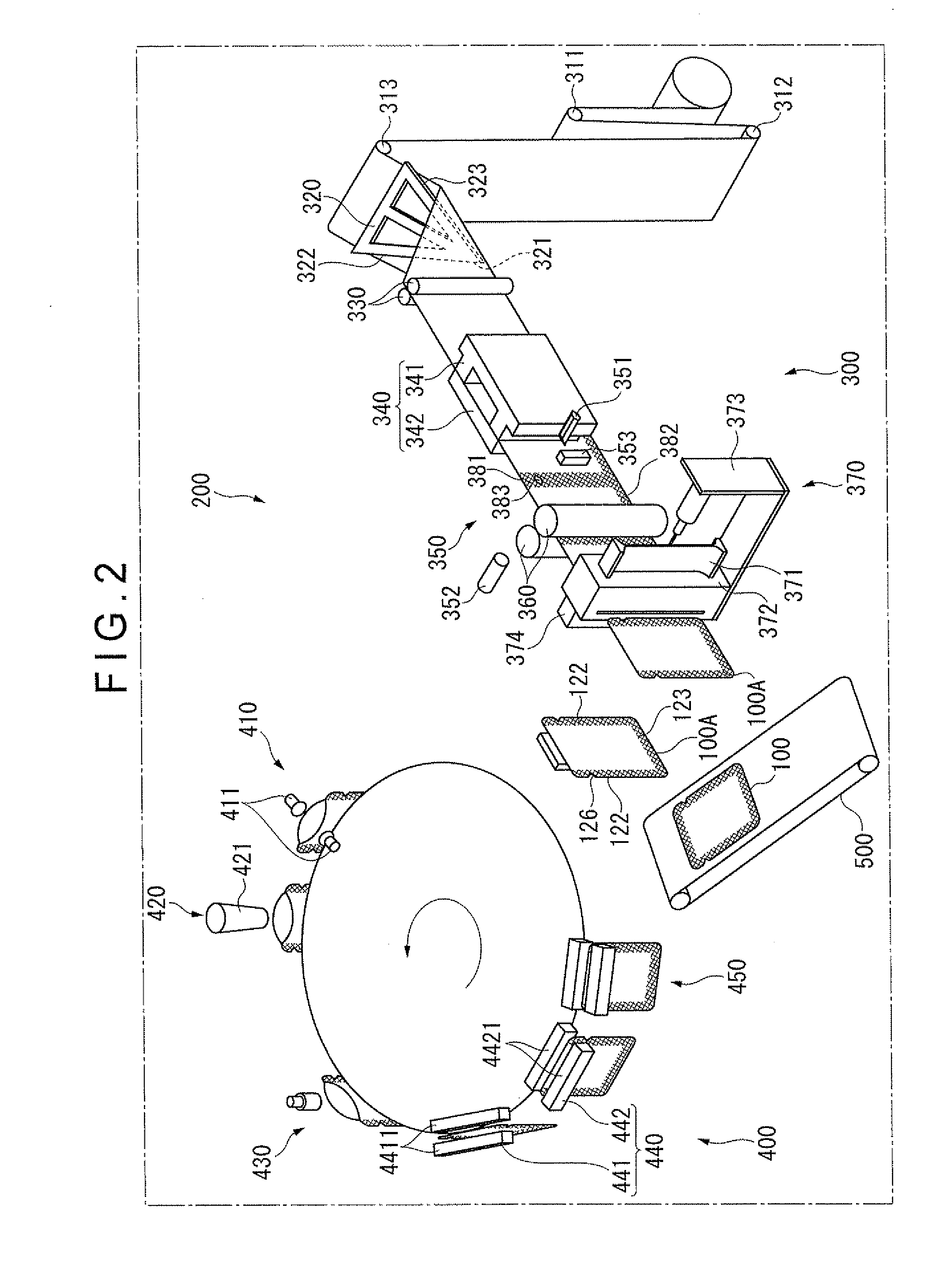
[0055]Embodiments of the present invention will be described below with reference to the attached drawings.

[1. Structure of Packaging Bag 100]

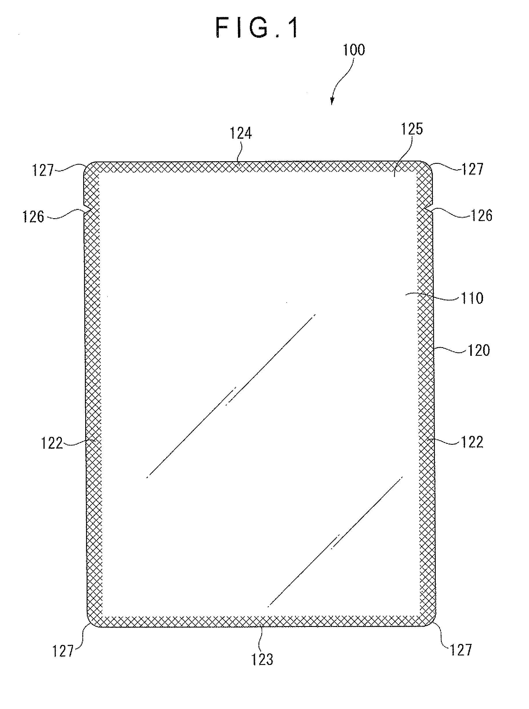
[0056]FIG. 1 is a front view of a packaging bag according to an exemplary embodiment of the invention.

[0057]As shown in FIG. 1, a packaging bag 100 includes: a bag body 120 that is obtained by superposing base films 110 as a packaging material and forming side seal portions 122, a bottom seal portion 123 and a top seal portion 124 on the periphery of the base films; a notch 126 provided on the side seal portions 122 closer to an opening 125 of the bag body 120; and rounded portions 127 formed in a substantially arc at four corners of the bag body 120.

[0058]The base film 110 may be: a film made of polyethylene terephthalate (PET), nylon (Ny) and cast polypropylene (CPP); a film made of PET, aluminum (AL) foil and CPP; a film made of PET, Ny and L-LDPE; a transparent vapor-deposited film made of PET and L-LDPE; or a film made of Ny, ethylene vin...


PUM

PropertyMeasurementUnit
thicknessaaaaaaaaaa
thicknessaaaaaaaaaa
thicknessaaaaaaaaaa

Abstract

A cutter includes a male blade, a female blade, an advancement and retraction controller and a suction device. The male blade includes: a linear cutting portion linearly shaped with a predetermined thickness in a center part; a rounded cutting portion where a radius having a substantially arc shape in planar view is continuously formed from the linear cutting portion; and an end provided adjacent to the rounded cutting portion. The female blade has a fitting portion that is a hole conforming to the profile of the male blade in planar view and to which the male blade is fitted. On a lateral side of the female blade, an elongated hole for inserting a base film from one lateral side to the other lateral side is formed as an insertion portion.

Description

TECHNICAL FIELD[0001]The present invention relates to a cutter of a packaging bag having a seal portion on a periphery, a manufacturing device of the packaging bag and a manufacturing method of the packaging bag.BACKGROUND ART[0002]As a packaging material for packaging foods, pharmaceutical and medical products and groceries, a four-side-sealed packaging bag is known. Such a four-side-sealed packaging is provided by sealing two base films of a quadrangular bag body at four sides. The packaging bag has four sharp corners, which may hurt a hand or make runs in stockings and the like. Accordingly, a technique to cut the four corners in a substantially arc shape has been widespread.[0003]For a manufacturing device of a packaging bag, an outline process in which devices are individually operated and an inline process in which devices are incorporated in a process line to manufacture a roll of packaging bags are available.[0004]In the outline process, as shown in FIG. 10A, after sealing s...

Claims


Application Information

Patent Timeline
Patent Type & Authority Applications(United States)
IPC IPC(8): B31B49/04B31B19/14B31B19/60B31B50/02B31B50/16B31B50/20B31B50/22B31B70/00
CPCB26D1/0006B65B61/18B26D2001/006B26F1/40B26F1/44B26F2001/4481B31B19/16B31B23/00B31B2219/145B31B2219/148B31B2237/10B31B2237/40B31B2237/406B65B5/022B65B43/04B65B43/465B65B43/50B65B61/06B26D3/10B31B70/00B31B2160/10B31B70/16B31B2155/00B31B70/148B31B2155/001B31B2155/0014Y10T83/9447B31B50/14B31B2160/106
Inventor GOTO, SHUICHI
Owner IDEMITSU UNITECH CO LTD
Learn More