Optical engine driving belt tightening device

A technology of optical engine and tensioning device, applied in transmission device, mechanical equipment, belt/chain/gear and other directions, can solve the problem of inconvenient installation of tensioning mechanism, achieve simple processing and installation of mechanical structure, meet frequent disassembly and assembly, The effect of quick disassembly

Inactive Publication Date: 2017-09-01
TIANJIN UNIV
View PDF7 Cites 10 Cited by
  • Summary
  • Abstract
  • Description
  • Claims
  • Application Information

AI Technical Summary

Problems solved by technology

[0005] The purpose of the present invention is to provide a tensioning device for the transmission belt of an optical engine, which

Method used


Image

  • Optical engine driving belt tightening device
  • Optical engine driving belt tightening device
  • Optical engine driving belt tightening device

Examples


Embodiment Construction

[0015] The principle and structure of the present invention will be further described below in conjunction with the accompanying drawings and through embodiments.

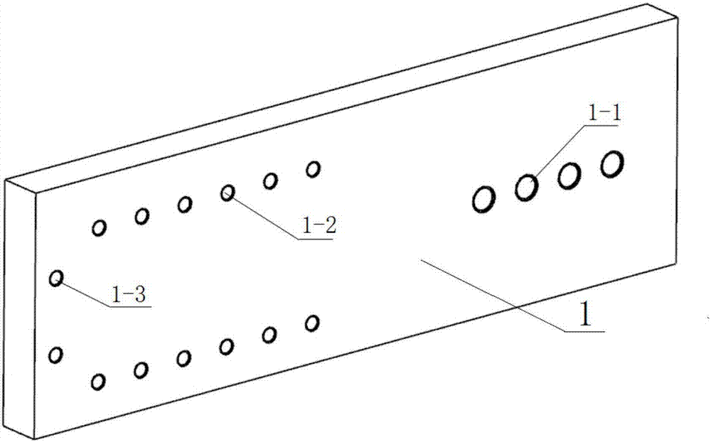
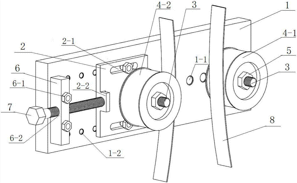
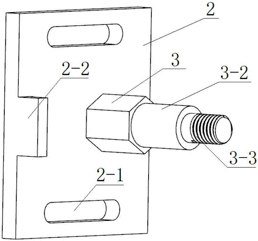
[0016] Optical motor toothed belt tensioning device, its structure is: the right side of mounting plate 1 is provided with first mounting hole 1-1; The left side of mounting hole is provided with the 3rd mounting hole 1-3 (as figure 1 ). The mobile plate 2 is respectively provided with elongated holes 2-1 up and down, the position in the middle is provided with threaded holes 2-3, and the position perpendicular to the elongated holes of the mobile plate is provided with a boss 2-2. The bolts pass through the long holes, and then the mobile plate is pre-tightened and fixed on the second mounting hole (such as image 3 ). The long thread section 3-1 of an idler shaft bolt 3 is screwed into the first mounting hole, the right idler wheel 4-1 is installed on the idler shaft section 3-2, and the lock nut 5 is screwed ...


PUM


Abstract

The invention discloses an optical engine toothed belt tightening device. According to the structure of the optical engine toothed belt tightening device, an installing plate is provided with three types of threaded holes, the upper portion and the lower portion of a moving plate are each provided with a long-strip hole, the middle position of the moving plate is provided with a threaded hole, and a convex table is arranged on the position, perpendicular to the long-strip holes of the moving plate, of the moving plate. Bolts penetrate through the long-strip holes to fix the moving plate to second installing holes. An idler shaft bolt is screwed into a first installing hole and fixes a right side idler shaft, the other idler shaft bolt is screwed the threaded hole in the middle of the moving plate, and other operations of the idler shaft bolt is in accordance with an installing structure of the right side idler shaft. A strip-shaped support is fixed to third installing holes through bolts, one face of the strip-shaped support is provided with two through holes, and the other face of the strip-shaped support is provided with a threaded hole. The adjusting bolt is screwed into the threaded hole to abut against the convex table position of the moving plate, and tightening degree adjustment of a driving belt is achieved. Disassembling of the driving belt is achieved only by loosening the adjusting bolt, and other parts do not need to be disassembled. It is guaranteed that the driving belt is tightened, and meanwhile the frequent disassembling and assembling requirement of the driving belt of an optical engine can be met.

Description

technical field [0001] The invention belongs to the engine structure technology, and in particular relates to a design structure for tensioning an optical engine drive belt. Background technique [0002] Visual research on detailed information such as flow, spray, mixing, and combustion in the engine cylinder has always been a hot technology pursued at home and abroad, so engines with in-cylinder visualization windows are often called "optical engines", and now this device is being widely used In the diagnosis of air flow movement, mixture formation and combustion in the cylinder. The use of laser and high-speed camera to obtain in-cylinder combustion information through the visualization window has important guiding significance for the study of the actual working process and entity development in the engine cylinder. [0003] The engine opens or closes the intake and exhaust valves through the rotation of the camshaft. The movement of the camshaft is transmitted by the po...

Claims


Application Information

Patent Timeline
IPC IPC(8): F16H7/08
CPCF16H7/08
Inventor 王天友孙彦哲文明鲁帧
Owner TIANJIN UNIV
Why Eureka
Try Eureka