
Display apparatus

A technology of a display device and a display area, which is applied to instruments, electrical digital data processing, and input/output processes of data processing, etc. Poor, inaccurate pressing force and other problems, to achieve the effect of increasing usability, convenient operation and precise control

Inactive Publication Date: 2017-09-01
INNOLUX CORP
View PDF7 Cites 1 Cited by
  • Summary
  • Abstract
  • Description
  • Claims
  • Application Information

AI Technical Summary

Problems solved by technology

However, capacitive pressure sensing technology and 2D touch sensing electrodes have limitations in terms of architecture. Generally, the pressure sensing structure needs to be placed on the side of the display panel away from the display surface (below the display panel) to avoid The electric field interference of the pressure sensing structure causes the sensing sensitivity of the touch sensing electrode to deteriorate
However, if the pressure sensing structure is arranged on the side of the display panel away from the display surface, the sensing sensitivity of the pressure sensing structure itself will be poor, so that the sensed pressing force will be inaccurate, resulting in malfunctions

Method used


Image

  • Display apparatus
  • Display apparatus
  • Display apparatus

Examples


Embodiment Construction

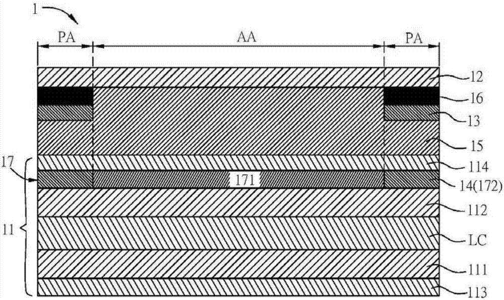
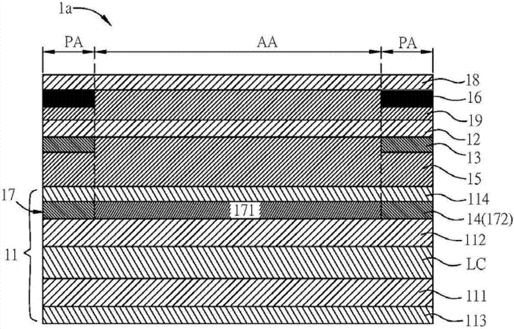
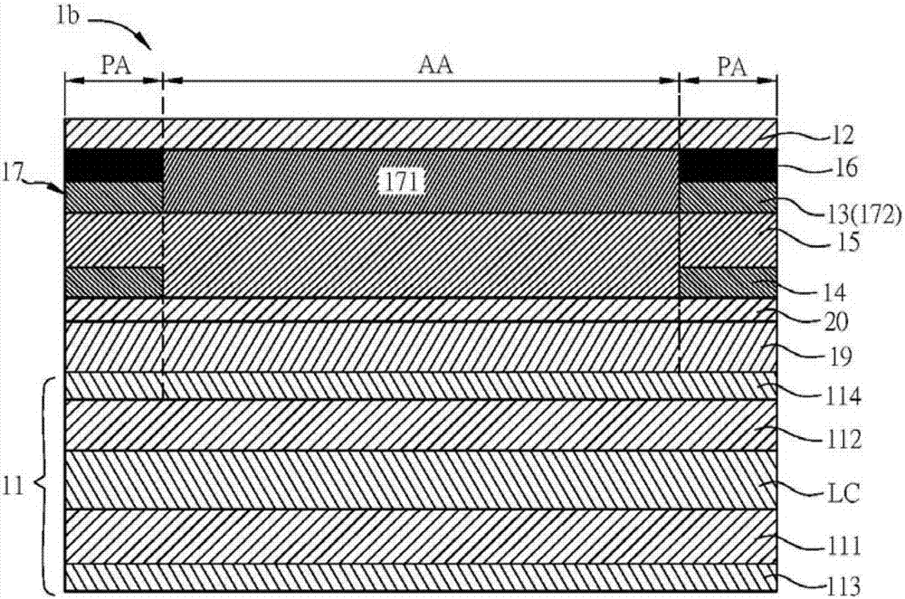
[0030] A display device according to a preferred embodiment of the present invention will be described below with reference to related drawings, wherein the same elements will be described with the same reference symbols. The illustrations of all the implementation aspects of the present invention are only schematic representations, and do not represent real dimensions and proportions. In addition, the orientations "up" and "down" in the following embodiments are only used to represent relative positional relationships. Furthermore, "on", "over", "under" or "under" that an element is formed on another element may include that one element is in direct contact with another element in an embodiment, or may also include that one element is in contact with another element. There are other additional elements between one element so that one element does not have direct contact with another element. In addition, an element "facing" another element may include an embodiment in which ...


PUM


Abstract

Disclosed is a display apparatus. The display apparatus comprises a display panel, a first substrate, a first pressure electrode layer, a second pressure electrode layer and a compression layer; the display panel has a display region and a peripheral region positioned on the periphery of the display region; the first substrate is arranged opposite to the display panel; the first pressure electrode layer is arranged on one side, towards the display panel, of the first substrate, and is corresponding to the peripheral region; the second pressure electrode layer is arranged on one side, towards the first substrate, of the display panel; and the compression layer is sandwiched between the first pressure electrode layer and the second pressure electrode layer.

Description

technical field [0001] The present invention relates to a display device, in particular to a display device with pressure sensing function. Background technique [0002] With the continuous advancement of science and technology, various information devices are constantly being introduced, such as mobile phones, tablet computers, ultra-thin notebook computers, and satellite navigation. In addition to generally using a keyboard or a mouse for input or manipulation, using touch technology to manipulate an information device is a rather intuitive and popular manipulation method. Among them, the touch device has a humanized and intuitive input operation interface, so that users of any age can directly select or control information equipment with their fingers or stylus. [0003] Today's touch technology is mostly two-dimensional (2D) plane multi-touch (Multi-Touch), which uses, for example, a finger to touch the display surface to accurately determine the touch position of the f...

Claims


Application Information

Patent Timeline
Patent Type & Authority Applications(China)
IPC IPC(8): G06F3/041G06F3/044
CPCG06F3/0412G06F3/0414G06F3/044
Inventor 詹孟学简文洋刘念恩林家进郑秉绪
Owner INNOLUX CORP
Learn More