Three-hole carbon brush box apparatus of high-power wind power generator

A technology of wind generators and brush boxes, applied in the direction of electromechanical devices, electrical components, electric components, etc., can solve problems such as burning equipment, insufficient power, and inability to meet high-power slip ring current transmission, and achieve the effect of avoiding electrical failures

Pending Publication Date: 2017-09-01
摩腾科技(上海)有限公司
View PDF4 Cites 1 Cited by
  • Summary
  • Abstract
  • Description
  • Claims
  • Application Information

AI Technical Summary

Problems solved by technology

[0002] At present, the carbon brush holder device used in wind farms is a double-hole carbon brush box device structure, which is suitable for the current transmission of ordinary slip rings. This structure occupies a small space, but it cannot meet the current transmission of high-power slip rings. All are adding high-power equipment, so they cannot meet market demand
There are problems under normal use: 1. Insufficient power will cause the carbon brush current to be overloaded during the use of the product, which will easily cause high temperature and burn out equipment failures; 2. The distribution is dense, there are many linear contact points, and there is aggravated slip ring wear , heat generation, carbon brush expansion, etc., resulting in a high failure rate; 3. The assembly of multiple brush boxes does not have integrity. There are multiple points of force on the brush box on the support frame, and the equipment is prone to vibration during high-speed operation, resulting in carbon brush failure. Intermittent contact with the slip ring surface can easily lead to ignition failures; 4. Cannot meet the needs of high-power equipment

Method used


Image

  • Three-hole carbon brush box apparatus of high-power wind power generator
  • Three-hole carbon brush box apparatus of high-power wind power generator
  • Three-hole carbon brush box apparatus of high-power wind power generator

Examples


Embodiment Construction

[0013] The embodiments of the three-hole carbon brush box device of the high-power wind generator of the present invention will be further described below with reference to the accompanying drawings.

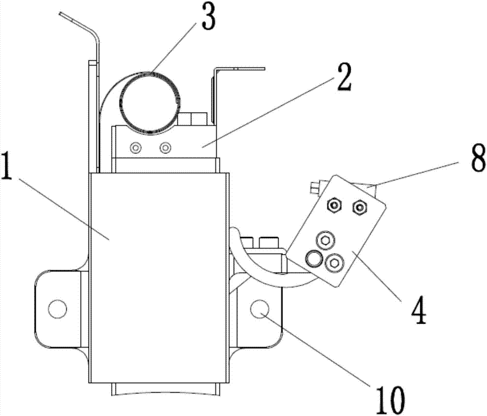
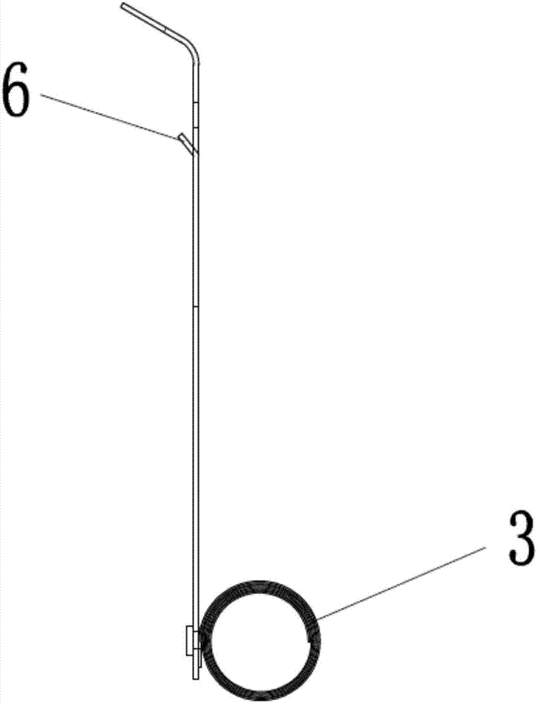
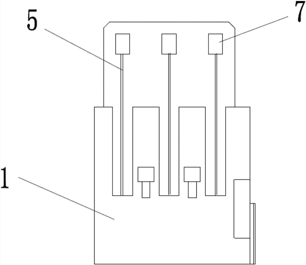
[0014] A three-hole carbon brush box device for a high-power wind generator, comprising a brush box body, a carbon brush 2, a compression spring 3, and a contact alarm switch 4. The brush box body is an integrated brush box 1, two parts of the integrated brush box 1. Both sides are provided with threaded mounting holes 10, and the integrated brush box 1 is provided with three square openings 9 for installing carbon brushes 2, the compression spring 3 is an integrated constant pressure spring 3, and the contact alarm switch 4 is fixed in the integrated On the brush box 1, a groove 5 is provided on the other side of the integrated brush box 1, and the integral constant pressure spring 3 is pressed in the groove 5. One side of the integrated brush box 1 with the groove 5 is also provi...


PUM


Abstract

The invention discloses a three-hole carbon brush box apparatus of a high-power wind power generator. According to the technical main points, the three-hole carbon brush box apparatus comprises a brush box body, a carbon brush, a compression spring and a contact alarm switch; the brush box body is an integrated brush box; screw thread mounting holes are formed in the two sides of the integrated brush box respectively; three square openings used for placing the carbon brush are formed in the integrated brush box; the compression spring is an integrated constant compression spring; the contact alarm switch is fixed on the integrated brush box; grooves are formed in the other side of the integrated brush box; and the integrated constant compression spring is arranged in the grooves in a pressing manner. The three-hole carbon brush box apparatus has the advantages as follows: the brush box achieves a main body fixation effect; the constant compression spring is inserted in the grooves in one side of the brush box for playing a role of conveying pressure to the carbon brush; the contact alarm switch is fixed on one side of the brush box to play a role of giving out an alarm when the normal service life limit of the carbon brush is reached so as to remind an operator to replace the carbon brush in time, thereby protecting the whole system and avoiding occurrence of electrical faults.

Description

Technical field [0001] The invention relates to a wind power generator component, more specifically, it relates to a three-hole carbon brush box device for a high-power wind power generator. Background technique [0002] At present, the carbon brush holder device used in wind power sites is a double-hole carbon brush box device structure, which is suitable for the current transmission of ordinary slip rings. This structure occupies a small space, but cannot meet the current transmission of high-power slip rings. All of them are adding high-power equipment, so they cannot meet market demand. There are problems under normal use: 1. Insufficient power, which will cause the product to overload the carbon brush current during use, which is prone to high temperature and burn the equipment; 2. The distribution is dense, there are many linear contact points, and slip ring wear is increased. , Heating, carbon brush expansion, etc., resulting in a high failure rate; 3. Multi-brush box ass...

Claims


Application Information

Patent Timeline
Patent Type & Authority Applications(China)
IPC IPC(8): H02K5/14H02K13/00
CPCH02K5/14H02K13/00
Inventor 王天子
Owner 摩腾科技(上海)有限公司
Why Eureka
Try Eureka