
Milling device and drive connecting assembly thereof

A technology for driving connection and connecting piece, applied in the field of milling device and its driving connection components, can solve the problems of screw wear, weak structure, milling cutter wear, etc., so as to reduce wear, achieve better milling effect, and increase contact area. Effect

Inactive Publication Date: 2017-09-05
惠州市格农科技有限公司
View PDF9 Cites 3 Cited by
  • Summary
  • Abstract
  • Description
  • Claims
  • Application Information

AI Technical Summary

Problems solved by technology

[0003] The traditional milling machine usually uses screws to fix the milling cutter. Since the screw is directly screwed into the milling cutter, the milling cutter and the drive connection part are fixed, and the drive connection part transmits the power of the driver to the milling cutter. The screw plays a role of fixing. During the power transmission, the screw also drives the milling cutter at the same time. On the one hand, the milling cutter with screw holes is less fragile in structure and is easy to break when subjected to huge torque. On the other hand, the long-term cooperation between the screw and the milling cutter is likely to cause screw Wear and milling cutter wear, which in turn makes the connection between the two stable, and it is easy to make the milling cutter shake or even fall off, causing damage to the workpiece

Method used


Image

  • Milling device and drive connecting assembly thereof
  • Milling device and drive connecting assembly thereof
  • Milling device and drive connecting assembly thereof

Examples


Embodiment Construction

[0026] In order to facilitate the understanding of the present invention, the present invention will be described more fully below with reference to the associated drawings. Preferred embodiments of the invention are shown in the accompanying drawings. However, the present invention can be embodied in many different forms and is not limited to the embodiments described herein. On the contrary, the purpose of providing these embodiments is to make the disclosure of the present invention more thorough and comprehensive.

[0027] It should be noted that when an element is referred to as being “disposed on” another element, it may be directly on the other element or there may also be an intervening element. When an element is referred to as being "connected to" another element, it can be directly connected to the other element or intervening elements may also be present. The terms "vertical," "horizontal," "left," "right," and similar expressions are used herein for purposes of ...


PUM


Abstract

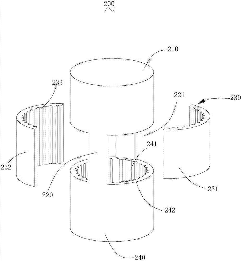
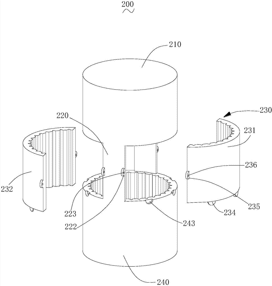
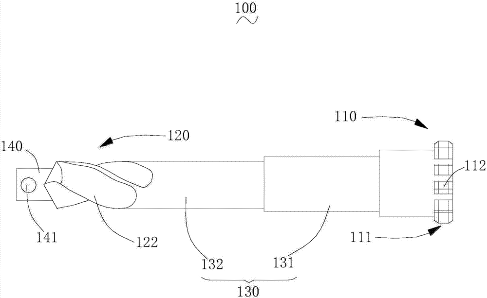
The invention relates to a milling device and a drive connecting assembly thereof. The drive connecting assembly comprises a drive shaft, a connecting part, a fixed sleeve part and a limiting sleeve; the drive shaft is connected with the limiting sleeve through the connecting part, a limiting hole is formed in the limiting sleeve, multiple first limiting keys are arranged on the side wall of the limiting hole, the two sides of the connecting part are each provided with a containing groove, the fixed sleeve part comprises a first sleeve part and a second sleeve part, the first sleeve part and the second sleeve part are arranged in the two containing grooves, the inner surface of the first sleeve part and the inner surface of the second sleeve part are each provided with multiple second limiting keys, and the second limiting keys are staggered from the first limiting keys. Through the drive connecting assembly, power of a driver can be transmitted to a milling cutter, through spline fit of the second limiting keys and a milling cutter, the contact area between the drive connecting assembly and the milling cutter can be effectively increased, wear can be effectively reduced, the milling cutter can be more stable after working for a long time, and the milling effect is better.

Description

technical field [0001] The invention relates to the technical field of milling, in particular to a milling device and a driving connection assembly thereof. Background technique [0002] Milling cutter is a tool used for polar milling of workpieces. Milling cutters generally have one or more teeth and mill workpieces in high-speed rotation. They are mainly used to process planes, steps, grooves, and formed surfaces on milling machines. and cut workpieces, etc. [0003] The traditional milling machine usually uses screws to fix the milling cutter. Since the screw is directly screwed into the milling cutter, the milling cutter and the drive connection part are fixed, and the drive connection part transmits the power of the driver to the milling cutter. The screw plays a role of fixing. During the power transmission, the screw also drives the milling cutter at the same time. On the one hand, the milling cutter with screw holes is less fragile in structure and is easy to break ...

Claims


Application Information

Patent Timeline
Patent Type & Authority Applications(China)
IPC IPC(8): B23C5/26B23C9/00B23Q3/12B23P23/02
CPCB23C5/26B23C9/00B23P23/02B23Q3/12
Inventor 温玉友
Owner 惠州市格农科技有限公司
Learn More