Detaching device for rotating shaft of steel casing motor with clamping function

A technology for motor shafts and dismantling devices, applied to workpiece clamping devices, hand-held tools, manufacturing tools, etc., can solve the problems of reducing the secondary utilization rate of the shaft, scrapping the rotor, and easy relative displacement, etc., to avoid excessive shaft head It is difficult to insert the bearing, prevent the shaft head from becoming larger or the shaft is damaged, and improve the effect of secondary reuse rate

Inactive Publication Date: 2017-09-05
严梓展
View PDF0 Cites 10 Cited by
  • Summary
  • Abstract
  • Description
  • Claims
  • Application Information

AI Technical Summary

Problems solved by technology

[0002] During the production process of the motor, there are often rotor problems that cause the rotor to be scrapped. For the scrapped rotor, the shaft needs to be disassembled and reused. The relative displacement causes the extrusion head to squeeze the end face of the cast aluminum rotor. At the same time, the rotor collapses due to uneven force during the withdrawal process, which has a great impact on the safety of the operator. At the same time, if the shaft is not coated after the withdrawal Oil treatment, the shaft is easy to rust, reducing the secondary utilization of the shaft

Method used


Image

  • Detaching device for rotating shaft of steel casing motor with clamping function
  • Detaching device for rotating shaft of steel casing motor with clamping function
  • Detaching device for rotating shaft of steel casing motor with clamping function

Examples


Embodiment Construction

[0020] The technical scheme of this patent is described in further detail below in conjunction with specific embodiments

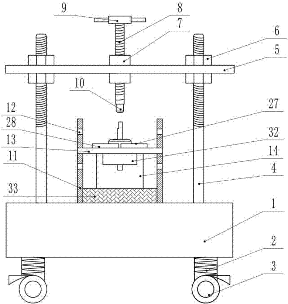
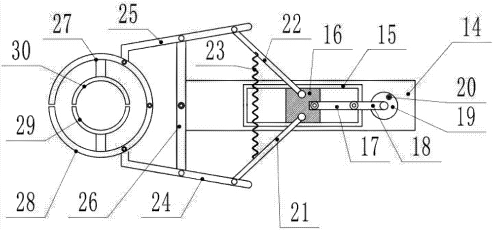
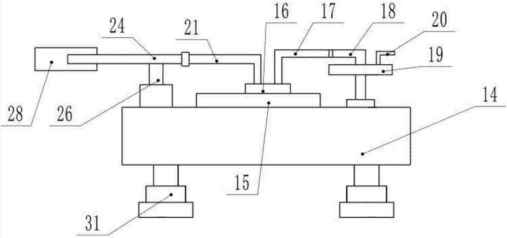
[0021] see Figure 1-4 , an iron shell motor shaft removal device with a clamping function, including a machine 1, an adjusting screw 4, a support plate 5, a screw 8, a rotating handle 9, an extrusion head 10, a dismounting table 11, a limit groove 12, Bearing table 14, slide rail 15, positive clamping hand 29, auxiliary clamping hand 30, oiling device 32 and sponge 33, described machine table 1 lower side is fixedly installed shock-absorbing leg 2, and shock-absorbing leg 2 is provided with at least four groups, A universal wheel 3 is fixedly installed under the vibration support foot 2, and a limit locking device is installed on the universal wheel 2 to prevent the device from moving during work; Set four groups, the upper and lower parts of the adjusting screw 4 are tapped with threads, the adjusting screw 4 is fixedly connected with the machine table ...


PUM


Abstract

The invention discloses a dismantling device for a rotating shaft of an iron shell motor with a clamping function, which includes an extrusion head, a dismantling table, a limit groove, a bearing table, a slide rail, a positive clamping hand, a secondary clamping hand, an oiling device and a sponge. A disassembly platform is fixedly installed at the center of the upper surface of the machine table, and a sponge is provided at the inner bottom of the disassembly table; For the slider, the inner walls of the first arc plate and the second arc plate are fixedly connected to the opposite side of the positive gripper and the auxiliary gripper through a connecting rod; an oiling device is fixedly installed under the limiting plate. The rotor is clamped during the disassembly process of the shaft to prevent the relative displacement of the rotor in the process of withdrawing the shaft, which will cause the extrusion head to squeeze the end face of the cast aluminum rotor, and it can also prevent the rotor from collapsing due to uneven force during the process of withdrawing the shaft , improve the safety of operation.

Description

technical field [0001] The invention relates to the field of motors, in particular to a dismantling device for a rotating shaft of an iron shell motor with a clamping function. Background technique [0002] During the production process of the motor, there are often rotor problems that cause the rotor to be scrapped. For the scrapped rotor, the shaft needs to be disassembled and reused. The relative displacement causes the extrusion head to squeeze the end face of the cast aluminum rotor. At the same time, the rotor collapses due to uneven force during the withdrawal process, which has a great impact on the safety of the operator. At the same time, if the shaft is not coated after the withdrawal Oil treatment, the shaft is easy to rust, reducing the secondary utilization of the shaft. Contents of the invention [0003] The object of the present invention is to provide a device for removing the rotating shaft of an iron-cased motor with a clamping function, so as to solve ...

Claims


Application Information

Patent Timeline
Patent Type & Authority Applications(China)
IPC IPC(8): B25B27/02B25B11/00
CPCB25B27/023B25B11/00
Inventor 严梓展
Owner 严梓展
Why Eureka
Try Eureka