Method for producing a bore, a component and a fuel injector

A technology for fuel injectors and components, which is applied in the field of drilling holes, can solve problems such as strength reduction and difficulty, and achieve the effects of reducing the strength of valve parts and increasing manufacturing costs.

Active Publication Date: 2017-09-05
ROBERT BOSCH GMBH
View PDF11 Cites 0 Cited by
  • Summary
  • Abstract
  • Description
  • Claims
  • Application Information

AI Technical Summary

Problems solved by technology

This residual tensile stress reduces the strength of the component or valve part in the area of ​​the newly hardened zone or the discharge restriction

Method used


Image

  • Method for producing a bore, a component and a fuel injector
  • Method for producing a bore, a component and a fuel injector
  • Method for producing a bore, a component and a fuel injector

Examples


Example Embodiment

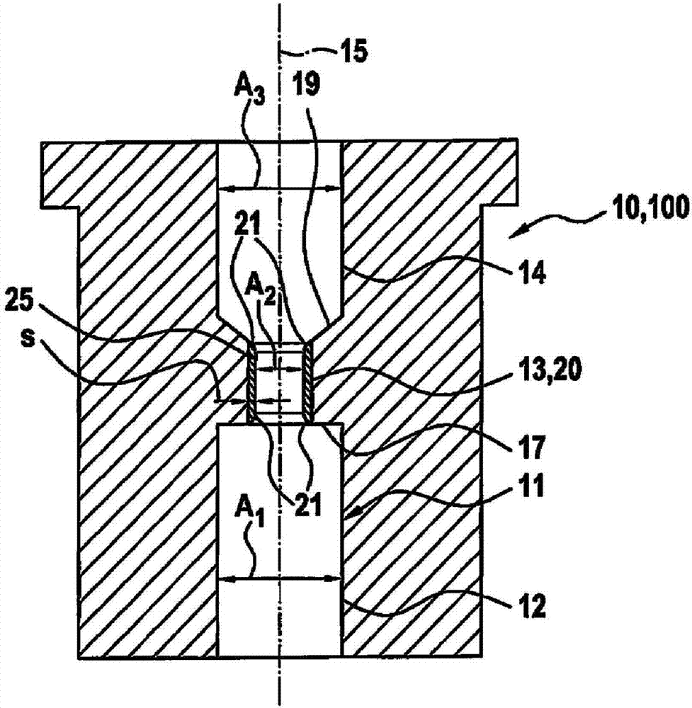
[0018] figure 1 The valve member 10 made of steel of the fuel injector 100 not shown in other respects is shown in simplified form, and the fuel injection valve is used as a so-called common rail system for injecting fuel into the combustion chamber of an internal combustion engine. component. The internal combustion engine is a self-igniting internal combustion engine, wherein the system pressure also present in the region of the valve element 10 is preferably greater than 2000 bar.

[0019] The valve member 10 arranged inside the unillustrated housing of the fuel injector 100 is used in a known manner to control the entry of fuel discharged from the so-called control chamber into the low pressure region of the fuel injector 100 so as to thereby influence the nozzle needle. exercise. For purely illustrative purposes, reference may be made to the applicant's DE 10 2012 219 657 A1 in terms of the basic structure and function of such a fuel injection valve 100.

[0020] The valve m...


PUM


Abstract

The invention relates to a method for producing a bore (11) especially for a high-pressure pressure medium in a component (10) of a fuel injector (100), wherein the bore (11) havs a section (13) produced by erosion (10). The component, formed by steel, is subjected to a heat treatment serving to harden the component (10).

Description

technical field [0001] The invention relates to a method for producing boreholes. The invention also relates to a component designed as a valve part of a fuel injector, in which the borehole has been produced according to the method according to the invention, and to a fuel injector having the same. Background technique [0002] Methods for producing boreholes are already known from practice. In a known method, an outlet opening with an integrated outlet restriction is produced in the valve part of the fuel injector. The outlet opening connects the control chamber within the fuel injector to the low-pressure region, so that the throughflow of fuel at high pressure from the control chamber in the direction of the low-pressure region can influence or control the movement of the nozzle needle in a known manner. The drainage hole basically consists of three borehole sections, one of which is a central borehole section with a smaller cross-section or diameter forming the draina...

Claims


Application Information

Patent Timeline
IPC IPC(8): C21D9/00C21D1/18
CPCC21D1/18C21D9/0068C21D9/08
Inventor T·尼埃里克洛H·奥佩尔卡J·弗勒朗
Owner ROBERT BOSCH GMBH
Why Eureka
Try Eureka