High-speed planetary reducer used for new energy automobiles

A planetary reducer, new energy vehicle technology, applied in transmission parts, gear transmissions, belts/chains/gears, etc., can solve the problems of small transmission torque, cumbersome structure, low transmission efficiency, etc., and achieve low transmission temperature rise. , The effect of wide speed ratio range and large torque output

Inactive Publication Date: 2017-09-05
QINGDAO INFINITY PRECISION MACHINE
View PDF5 Cites 0 Cited by
  • Summary
  • Abstract
  • Description
  • Claims
  • Application Information

AI Technical Summary

Problems solved by technology

Products on the existing market mainly use parallel shaft gearboxes or are directly driven by motors. Direct drive by motors results in large volume, heavy weight, low transmission efficiency, high operating costs, unfavorable energy saving and environmental protection, and is not conducive to maintenance; parallel shaft reducers are used for deceleration Many transmission stages, complex structure, heavy structure, low transmission efficiency, small transmission torque, high noise, temperature rise and other disadvantages

Method used


Image

  • High-speed planetary reducer used for new energy automobiles
  • High-speed planetary reducer used for new energy automobiles
  • High-speed planetary reducer used for new energy automobiles

Examples


Embodiment 1

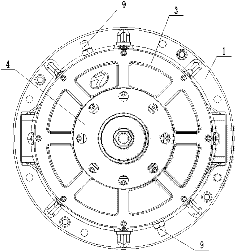
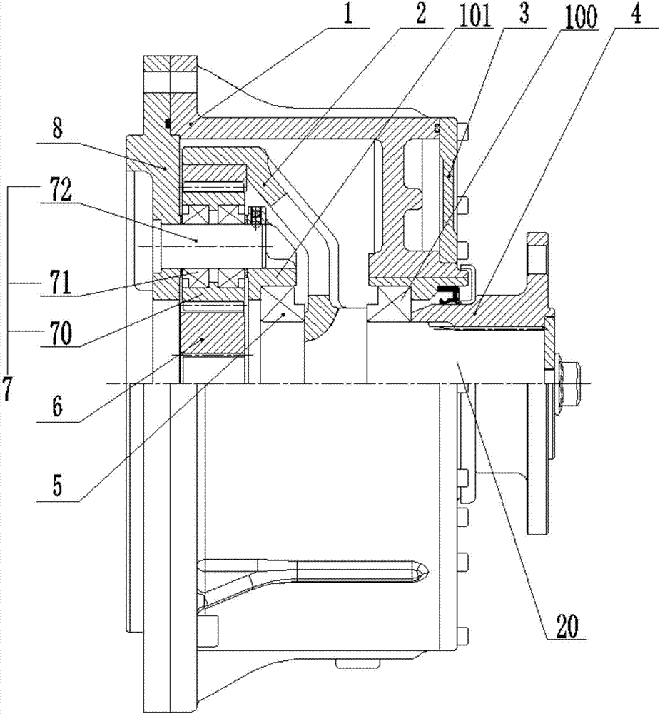
[0022] Such as figure 1 with figure 2 As shown, a high-speed planetary reducer for a new energy vehicle of this embodiment is characterized by comprising: reducer housing 1, output ring gear 2, output flange 4, sun gear 6, planetary gear set 7 and planetary gear The planet carrier 8 is fixedly connected to the reducer housing 1 by bolts, the output ring gear 2 is fixedly connected to the output shaft 20, and the output shaft 20 is connected to the reducer housing through the first bearing 100 1 Rotation connection, the output flange 4 is keyed to the output shaft 20, the planetary gear set 7 includes a planet gear 70, a second bearing 71 and a shaft 72, the shaft 72 is connected to the planet carrier 8, the planet The gear 70 is rotatably connected with the shaft 72 through the second bearing 71 and meshes with the output ring gear 2, and the sun gear 6 meshes with the planetary gear 70.

[0023] Preferably, at least three planetary gear sets 7 are evenly arranged around the sun...

Embodiment 2

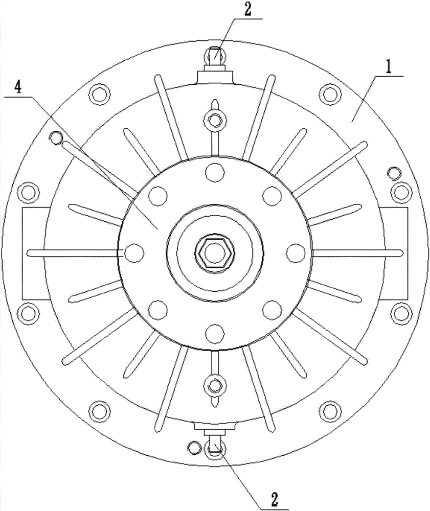
[0027] image 3 with Figure 4 As shown, a high-speed planetary reducer for a new energy vehicle is characterized by comprising: an inner ring gear seat 3, a reducer housing 1, an output flange 4, a planetary gear set 7, a planet carrier 8, a sun gear 9 and The inner gear 11, the inner gear seat 3 is fixedly connected to the reducer housing 1 by bolts, the inner gear 11 is fixed on the inner side of the inner gear seat 3, and the planet carrier 8 is opposite to the output shaft 20 In a fixed connection, the output shaft 20 is rotatably connected to the reducer housing 1 through a first bearing 100, the output flange 4 is keyed to the output shaft 20, and the planetary gear set 7 is mainly composed of a shaft 70 and a second bearing 71 It is composed of a planetary gear 72, the shaft 70 is connected to the planet carrier 8, the planetary gear 72 is rotatably connected to the shaft 70 through a second bearing 71, the planetary gear 72 meshes with the ring gear 11, the sun gear T...


PUM


Abstract

The invention relates to the field of reducers used for new energy automobiles such as pure electric automobiles and hybrid automobiles, in particular to a high-speed planetary reducer used for the new energy automobiles. The high-speed planetary reducer comprises a reducer box body, output gear rings, an output flange, a sun gear, a planet gear set and a planet carrier. The planet carrier is fixedly connected with the reducer box body through bolts. The output gear rings are fixedly connected with an output shaft. The output shaft is connected with the reducer box body through a first bearing in a rotating manner. The output flange is in key joint with the output shaft. The planet gear set comprises a planet gear, a second bearing and a shaft, wherein the shaft is connected with the planet carrier, and the planet gear is connected with the shaft through the second bearing in a rotating manner and is engaged with the output gear rings. The sun gear is engaged with the planet gear. One-stage planetary transmission is achieved, the speed ratio range is wide, the transmission efficiency is high, large-torque output can be achieved, and the structure is compact. A reducer shell comprises a water tank and a circulation water channel, circulating water cooling is adopted, and the transmission temperature rise of the reducer is low.

Description

Technical field [0001] The invention relates to the field of reducers for new energy electric vehicles such as pure electric vehicles and hybrid electric vehicles, in particular to a high-speed planetary reducer for new energy vehicles. Background technique [0002] Pollution emissions and traffic noise in cities are becoming more and more serious. Because new energy vehicles can effectively solve the two major problems of energy crisis and environmental pollution, new energy vehicles are the main direction for future automobile development. However, the domestic development level is still in a relatively backward stage, and the direct drive of the motor is mainly used, resulting in a relatively large motor structure, high cost, low drive efficiency and other adverse effects. The combined drive of the motor and reducer is currently in a blank, and some foreign companies have adopted it. The combined structure of the motor and the reducer is formed, but mainly parallel-shaft reduc...

Claims


Application Information

Patent Timeline
Patent Type & Authority Applications(China)
IPC IPC(8): F16H1/32F16H57/04
CPCF16H1/32F16H57/0415
Inventor 孙武装黄兴明赵东林王巧云李欠玲
Owner QINGDAO INFINITY PRECISION MACHINE
Why Eureka
Try Eureka