
Control device

A control device and protective cover technology, applied in the direction of electrical program control, sequence/logic controller program control, etc., can solve problems such as poor experience, loss of dust cover, complex structure, etc., to reduce costs and improve The effect of user experience

Pending Publication Date: 2017-09-05
UNIVERSAL WISDOM TECH BEIJING CO LTD
View PDF0 Cites 0 Cited by
  • Summary
  • Abstract
  • Description
  • Claims
  • Application Information

AI Technical Summary

Problems solved by technology

The existing screenless TV detachable lens cover does not provide a good operating experience, and the detachable lens cover is easy to lose the dust cover, which is inconvenient to operate and not beautiful
Compared with the separate lens cover, the advantage of the mechanical dust cover is that it will not be removed, but it also has the problem of bad experience
The best way is a fully automatic protective cover, which can completely make up for the above two deficiencies, but the biggest problem is high cost and complicated structure

Method used


Image

  • Control device
  • Control device
  • Control device

Examples


Embodiment Construction

[0019] The technical solutions of the present invention will be described in further detail below with reference to the accompanying drawings and embodiments.

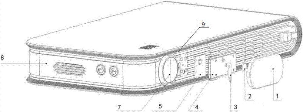
[0020] figure 1 It is an exploded view of the control device of the present invention, as shown in the figure, the control device includes:

[0021] Case 8, sliding piece 4, magnetic steel 2, protective cover 1 and Hall switch board 5.

[0022] The casing 8 has a slide rail 9 and a through hole, and the optical head of the optical machine accommodated in the casing 8 penetrates through the through hole;

[0023] Specifically, the casing 8 is the carrier of other components, such as the casing 8 carrying the slide rail 9 and the through hole, and the position of the through hole is consistent with the optical head of the optical machine arranged in the casing 8. Corresponding to the position of the optical machine head, the light beam emitted by the optical machine head is transmitted through the through hole.

[002...


PUM


Abstract

The embodiment of the invention relates to a control device. The control device comprises a machine shell, a sliding sheet, magnetic steel, a protection cover and a hall switch board, wherein the machine shell comprises a sliding rail and a through hole, and a buffing machine head of a buffing machine contained in the machine shell penetrates through the through hole; the sliding sheet is arranged in the sliding rail in a sliding mode and connected with the machine shell in a sliding mode; the magnetic steel is fixed on the sliding sheet; the protection cover is arranged on the sliding sheet in a covering mode, and therefore contains the magnetic steel; the hall switch board comprises a hall switch, and the hall switch is fixed on the machine shell; the sliding sheet slides behind the through hole through the sliding rail, and the protection cover covers the buffing machine head; when the sliding sheet slides behind the hall switch board through the sliding rail, the hall switch induces a magnetic filed generated by the magnetic steel, and therefore electrical signals are generated. By means of the control device, the effect of protecting a buffing machine shot can be achieved, and integrated on-off switching of a screen-free television is also achieved; meanwhile, user experiences are improved, and the cost is reduced.

Description

technical field [0001] The invention relates to the field of optoelectronic technology, in particular to a control device. Background technique [0002] The optical-mechanical lens projection of screenless TV is the core component that directly affects the viewing effect. Most of the optical and mechanical lenses of screenless TVs on the market are directly exposed, that is, there is no protection for the lens. The rest of the lens protection measures are nothing more than adding a separate protective cover and a mechanical manual protective cover to the housing. The existing detachable lens cover for screenless TVs does not provide a good operating experience, and the detachable lens cover is easy to lose the dust cover, which is inconvenient to operate and unattractive. Compared with the separate lens cover, the advantage of the mechanical dust cover is that it will not be removed, but it also has the problem of bad experience. The best way is a fully automatic protecti...

Claims


Application Information

Patent Timeline
IPC IPC(8): G05B19/04
CPCG05B19/04
Inventor 王伟杨攀刘星宇邹利科付强
Owner UNIVERSAL WISDOM TECH BEIJING CO LTD
Features
  • Generate Ideas
  • Intellectual Property
  • Life Sciences
  • Materials
  • Tech Scout
  • Unparalleled Data Quality
  • Higher Quality Content
  • 60% Fewer Hallucinations
Learn More