Common power supply system and method by using two power supply end devices

A technology of power supply end equipment and power receiving end equipment, which is applied in the field of using two power supply end equipment to jointly supply power, which can solve the problems of power receiving end equipment not working, POE power supply equipment instability, etc., and achieve the effect of increasing power

Inactive Publication Date: 2017-09-05
PHICOMM (SHANGHAI) CO LTD
View PDF3 Cites 4 Cited by
  • Summary
  • Abstract
  • Description
  • Claims
  • Application Information

AI Technical Summary

Problems solved by technology

[0009] The technical problem to be solved by the present invention is to provide a system and method that utilizes two power supply end devices to jointly supply power, so as to solve the problem that the power receiving end device cannot work due to the instability of a single power supply end device in traditional POE power supply

Method used


Image

  • Common power supply system and method by using two power supply end devices
  • Common power supply system and method by using two power supply end devices
  • Common power supply system and method by using two power supply end devices

Examples


Embodiment 1

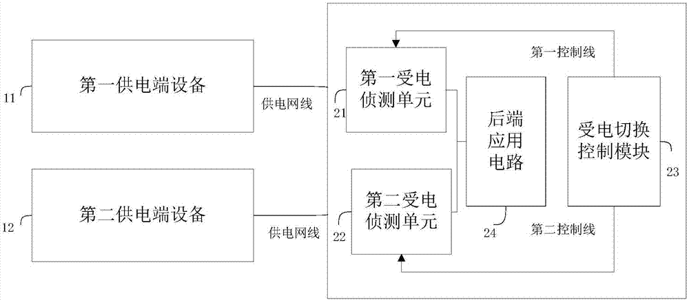
[0046] This embodiment provides a system that utilizes two power supply end devices to jointly supply power, such as image 3 As shown, it consists of the first power supply device, the second power supply device and the power receiving device, including:

[0047] The first power supply terminal device 11 is connected to the first power supply network port of the power supply terminal device, and is used to provide one circuit of power;

[0048] The second power supply end device 12 is connected to the second power supply network port of the power supply end device for providing another power supply;

[0049] The receiving end equipment includes:

[0050] The first power receiving detection unit 21 is used to feed back information to the power supply end device;

[0051] The second power receiving detection unit 22 is used to feed back information to the power supply end device;

[0052] The power receiving switching control module 23 is connected with the first power recei...

Embodiment 2

[0083] This embodiment provides a method of using two power supply end devices to jointly supply power, such as Figure 4 shown, including steps:

[0084] S11: Obtain two paths of power from two power supply devices;

[0085] S12: Determine whether the powers of the first power receiving detection unit and the second power receiving detection unit are within a preset power range;

[0086] If so, the power receiving switching control module selects one power supply according to the preset priority, and closes the other power supply;

[0087] If not, determine whether the first power receiving detection unit and the second power receiving detection unit are not in the preset power range, and if so, turn off two power supplies; otherwise, turn on one power supply within the preset power range .

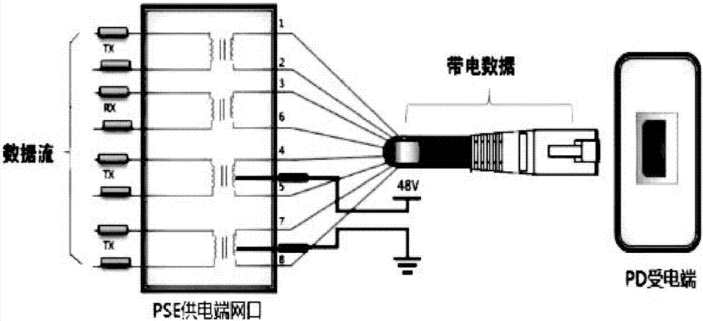
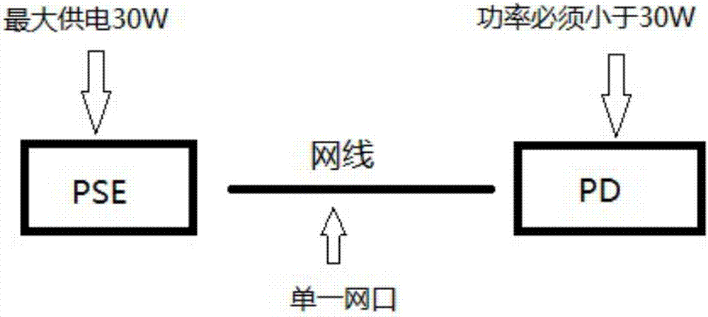
[0088] The power supply method in the prior art is a technical method in which a network cable is used to transmit data to the power receiving end device and supply power at the same ...

Embodiment 3

[0095] This embodiment provides a method of using two power supply end devices to jointly supply power, such as Figure 5 shown, including steps:

[0096] S21: Obtain two paths of power from two power supply devices;

[0097] S22: Determine whether the powers of the first power receiving detection unit and the second power receiving detection unit are within a preset power range;

[0098] If so, the power receiving switching control module selects one power supply according to the preset priority, and closes the other power supply;

[0099] If not, determine whether the first power receiving detection unit and the second power receiving detection unit are not in the preset power range, and if so, turn off two power supplies; otherwise, turn on one power supply within the preset power range .

[0100] S23: When it is detected that the power supply voltage of the current power supply device is lower than the preset voltage, turn on another power supply device to supply power....


PUM


Abstract

The invention discloses a common power supply system and method by using two power supply end devices for solving the problem that power receiving end devices cannot work because of the instability of a single power supply end device in the traditional POE power supply. The system is composed of a first power supply end device, a second power supply end device and a power receiving end device; the first power supply end device and the second power supply end device are separately connected with a first power supply network port and a second power supply network port of the power receiving end device for providing another path of electric power; the power receiving end device comprises a first power receiving detection unit used for feeding back information to the power supply end devices; a second power receiving detection unit used for feeding back information to the power supply end devices; and a power receiving switch control module connected with the first power receiving detection unit and the second power receiving detection unit at the same time and used for controlling the on-off of the power supply of the first power receiving detection unit and the second power receiving detection unit to a back end application circuit. By adoption of the common power supply system and method disclosed by the invention, non interruption of the transmission backup is ensured.

Description

technical field [0001] The present invention relates to the field of POE power supply, in particular to a system and method for jointly supplying power by two power supply end devices. Background technique [0002] POE is a technology that uses the power supply network cable to transmit data to the back-end equipment and supply power at the same time, so that the power receiving end equipment (referred to as PD) can work without additional power, such as figure 1 As shown, the power supply end equipment (referred to as PSE) is originally used for transmission of 4 pairs of wires, two of which add 48V voltage to the rear end of the network port transformer to supply power to the remote PD. [0003] In the actual POE power supply, the power supply device may be unstable, causing the power receiving device to fail to work. [0004] like figure 2 as shown, figure 2 It is a traditional POE power supply design schematic [0005] The power supply device and the power receivin...

Claims


Application Information

Patent Timeline
IPC IPC(8): H04L12/10
Inventor 何山
Owner PHICOMM (SHANGHAI) CO LTD
Why Eureka
Try Eureka