Micro drop jetting method and device

A droplet ejection and liquid ejection technology, which is applied to ejection devices, liquid ejection devices, etc., can solve the problems of affecting droplet ejection accuracy, inability to effectively control droplets, and droplet unevenness, etc., and achieves improved droplet ejection accuracy, Avoid the effect of extra droplet ejection

Active Publication Date: 2017-09-08
合肥铭传电子科技有限公司
View PDF6 Cites 4 Cited by
  • Summary
  • Abstract
  • Description
  • Claims
  • Application Information

AI Technical Summary

Problems solved by technology

[0006] The extra droplets in the current droplet ejection technology are considered to be an unstable phenomenon of droplet ejection, which brings many uncontrollable factors to droplet ejection and affects the accuracy of droplet ejection.
If the object to be sprayed is moving, the droplet spraying equipment cannot effectively control the droplets, resulting in uneven sprayed droplets

Method used


Image

  • Micro drop jetting method and device
  • Micro drop jetting method and device
  • Micro drop jetting method and device

Examples


Embodiment 1

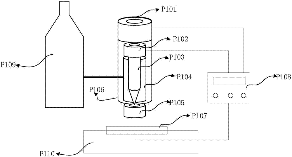
[0030] refer to figure 1 , a droplet spraying device, the device includes a brake P101, a vibrator P102, a cavity P104, a vibrating rod P103, a nozzle P105, a housing P106, a mobile platform P107, a controller P108, a liquid storage tank P109, and a fixed platform P110.

[0031] The brake P101 is above the vibrator P102, the vibrator P102 is connected to the vibrating rod P103, and the vibrating rod P103 is inserted into the cavity P104; the nozzle P105 is connected to the lower end of the cavity P104; the brake P101, the vibrator P101, the cavity P104, the vibrating rod P103, and the nozzle P105 Placed inside the shell P106; the controller P108 outputs a PWM signal which is amplified by the amplifier circuit and then sent to the brake P101. Driven by the PWM signal, the brake P101 pushes the vibrating rod P103 to make intermittent reciprocating linear motions, closing the nozzle P105 or opening The nozzle P105; the controller P108 outputs a PWM signal which is amplified by th...

Embodiment 2

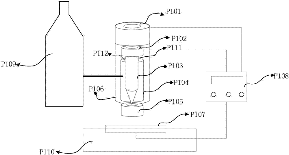
[0039] refer to figure 2 In this embodiment, on the basis of Embodiment 1, a spring P111 is placed on the top of the vibrating rod P103 and below the vibrator P102. The elastic force of the spring P111 can push up the vibrating rod P103 when the brake P101 is not pushed down, thereby opening the nozzle P105.

[0040]Before the controller P108 needs to control the movement of the mobile platform P107, if the area does not need to spray droplets, the controller P108 sends the strongest PWM signal in the positive direction to the brake P101, so that the brake P101 pushes the vibrating rod P103 downward to close the nozzle P105, prevent the liquid from overflowing, and stop sending the PMW signal to the vibrator P102 at the same time. At this time, send a PWM signal to the mobile station P107 to move the mobile station to the destination. After the movement is completed, when it is necessary to spray droplets again, the controller P108 stops outputting the PWM signal to the bra...

Embodiment 3

[0044] refer to image 3 , a droplet ejection method, the method comprising:

[0045] S101. According to the injection line pattern, the processor outputs two channels of PWM signals whose frequency, phase and pulse width can be continuously adjusted. The two channels of PWM signals are amplified by the amplifier circuit and applied to the vibrator and the brake respectively.

[0046] The droplet ejection device needs to adjust the PWM signal output by the controller according to the line type (such as a wide dotted line) that needs to be ejected. The signal sent to the vibrator needs to be adjusted according to the width of the line shape. When the droplet needs to be larger, the movement amplitude and frequency of the vibrator need to be smaller; when the droplet is small, the movement amplitude and frequency of the vibrator need to be larger. All of these can be realized by adjusting the PWM signal output by the controller.

[0047] S102. Driven by the PWM signal, the vib...


PUM


Abstract

The invention discloses a micro drop jetting device which comprises a brake, a vibrator, a cavity, a vibration rod, a jet nozzle and a shell. The brake is located above the vibrator. The vibrator is connected with the vibration rod. The vibration rod is sleeved with the cavity. The jet nozzle is connected with the lower end of the cavity. The vibrator is connected with the upper end of the cavity. The brake, the vibrator, the cavity, the vibration rod and the jet nozzle are arranged inside the shell. The brake is driven by a PWM signal to push the vibration rod to do intermittent reciprocating linear movement so that the jet nozzle can be closed or opened. The vibrator is driven by the PWM signal to drive the vibration rod to do periodic oscillatory motion, and continuous liquid is divided into micro drops. According to the micro drop jetting device, compared with the prior art, through the periodic oscillatory motion of the vibration rod, the continuous liquid is divided into the micro drops, in addition, the jet nozzle can be closed by pushing the vibration rod, the liquid is prevented from overflowing, and accordingly the jetting precision is improved.

Description

[0001] 【Technical field】 [0002] The invention relates to the field of micro-spraying of liquids, and more precisely relates to a method and device for spraying micro-droplets. [0003] 【Background technique】 [0004] With the rapid development of the industrial revolution, free forming technology has become increasingly mature, and has been widely used in product design, medical and industrial production and other fields, and has achieved huge economic benefits. Droplet jet free forming is an important branch of free forming technology. Its forming principle is mainly based on droplet jetting, that is, through external force, the forming material is sprayed from the nozzle to the substrate in the form of fine droplets to form two-dimensional graphics or three-dimensional entities. . According to the state of the ejected droplets, the droplet jet free forming system can be divided into two types: continuous type and on-demand type. When the controller sends out a spray signa...

Claims


Application Information

Patent Timeline
Patent Type & Authority Applications(China)
IPC IPC(8): B05B17/04B05B12/06
CPCB05B12/06B05B17/04
Inventor 彭文学刘宏
Owner 合肥铭传电子科技有限公司
Why Eureka
Try Eureka