Automatic disc placing and taking device and control system and method thereof
A disc and automatic technology, applied in the field of automation, can solve problems such as low efficiency and repeated monotonous testing process, and achieve the effect of improving production efficiency and reducing production costs
- Summary
- Abstract
- Description
- Claims
- Application Information
AI Technical Summary
Problems solved by technology
Method used
Image

Examples
Embodiment 1
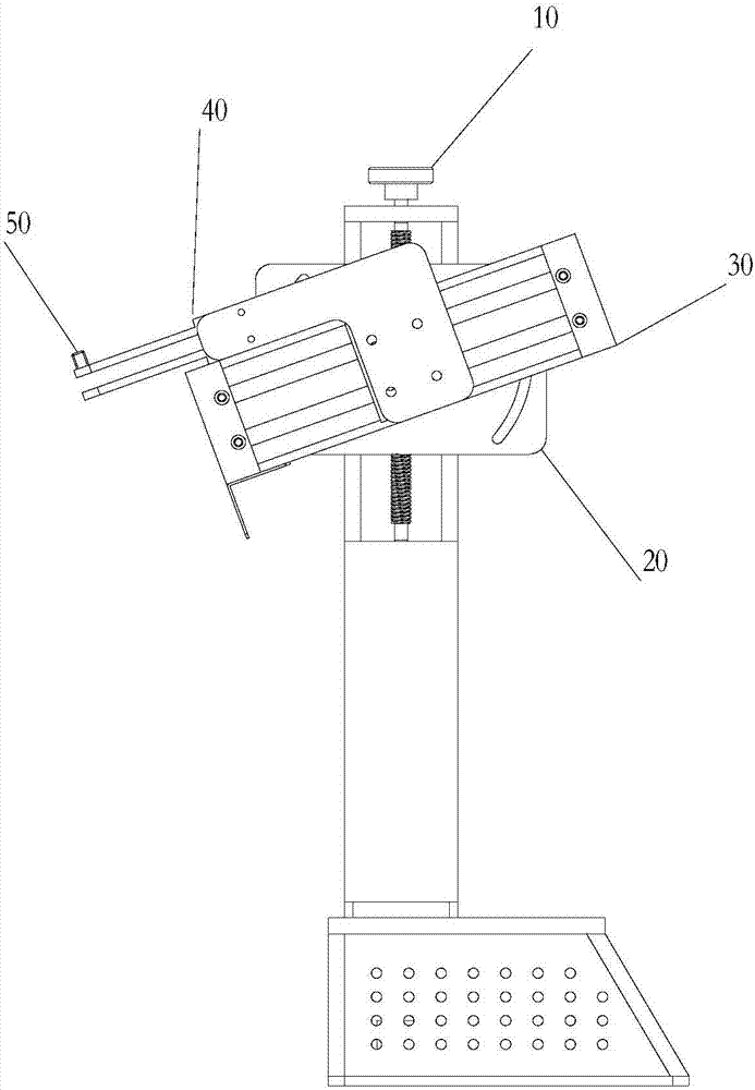
[0032] This embodiment provides an automatic disc loading and unloading device, such as figure 1 As shown, it includes: a height adjustment handle 10, an angle turntable 20, a forward and backward cylinder 30, a chuck cylinder 40 and a photoelectric sensor 50, wherein the angle turntable 20 is connected to the height adjustment handle 10, and the height adjustment The handle 10 is used to realize the height adjustment of the angle turntable 20, the advance and retreat cylinder 30 is connected with the angle turntable 20, the angle turntable 20 is used to realize the adjustment of the rotation angle of the advance and retreat cylinder 30, and the chuck The air cylinder 40 is connected with the forward and backward air cylinder 30, and the photoelectric sensor 50 is fixed on the disc clamping air cylinder 40, and the automatic loading and unloading action of the disc is realized through electrical cooperation.
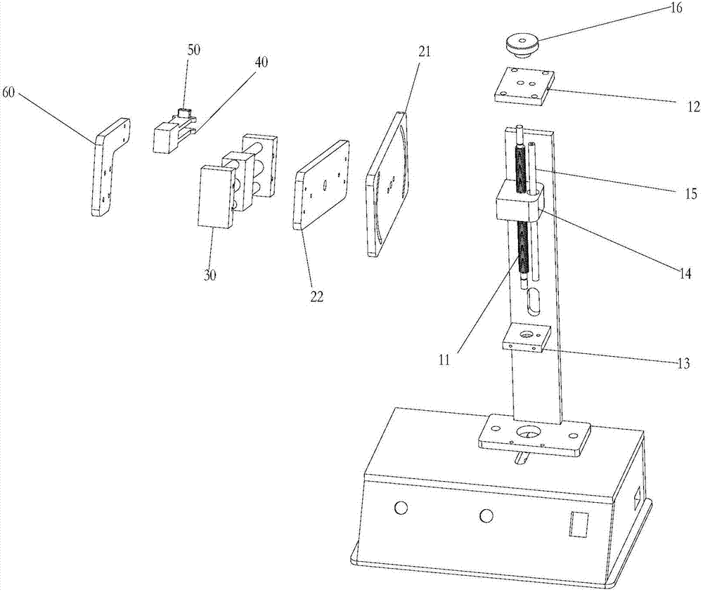
[0033] Can, but is not limited to, such as figure 2 As shown, the...
Embodiment 2
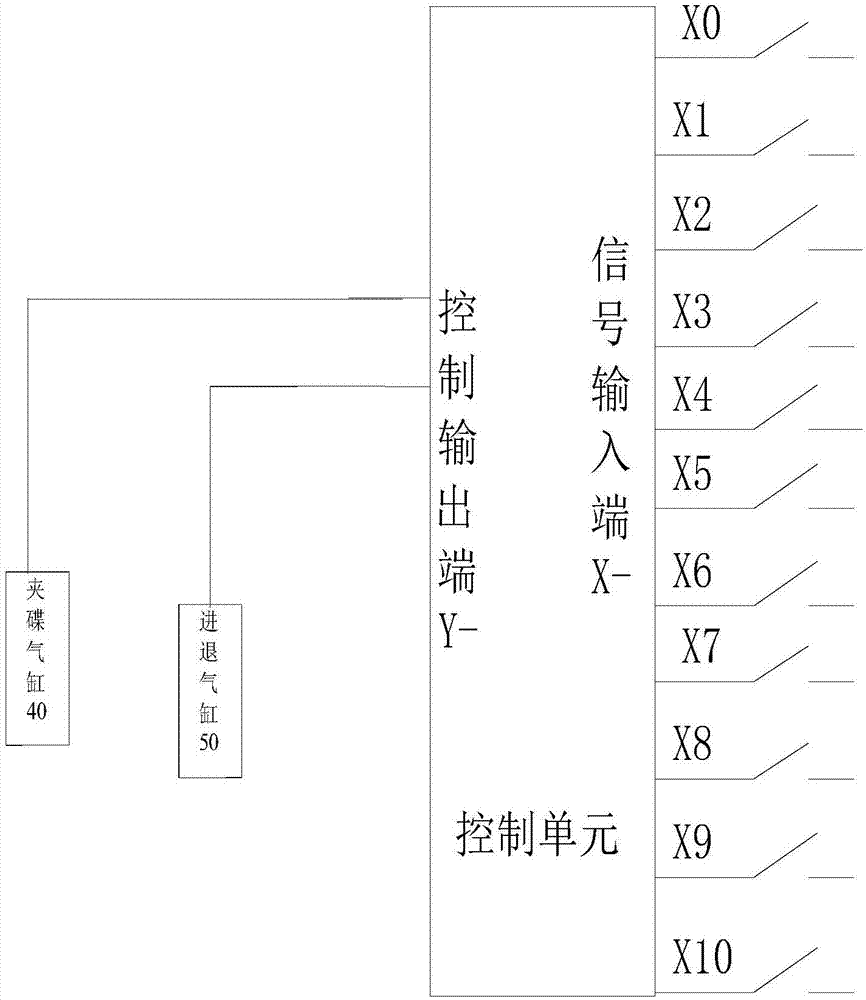
[0041] This embodiment provides a kind of control system for automatically putting and taking discs, such as image 3 As shown, including the above-mentioned automatic disc loading and unloading device and control unit,
[0042]The control unit includes an emergency stop switch signal interface X0, a manual disc clamping switch signal interface X1, a forward disc release signal interface X2, a forward position signal interface X3, a backward signal interface X4, a backward position signal interface X5, and detection of whether there is a disc Signal interface X6, disc clamping signal interface X7, disc clamping in-position switch signal interface X8, disc loosening signal interface X9, disc clamping in-position signal interface X10, the output terminal Y of the control unit is connected with the disc clamping cylinder 40 and the advancing and retreating cylinder 30 . It is possible, but not limited to, to send input signals to the control unit through an external control comp...
PUM
 Abstract
Description
Claims
Application Information
 - R&D
- Intellectual Property
- Life Sciences
- Materials
- Tech Scout
- Unparalleled Data Quality
- Higher Quality Content
- 60% Fewer Hallucinations
Browse by: Latest US Patents, China's latest patents, Technical Efficacy Thesaurus, Application Domain, Technology Topic, Popular Technical Reports.
© 2025 PatSnap. All rights reserved.Legal|Privacy policy|Modern Slavery Act Transparency Statement|Sitemap|About US| Contact US: help@patsnap.com