Adjustable mudguard for commercial vehicle and using method thereof
A fender and adjustable technology, which is applied to vehicle components, superstructure, and subassembly of the superstructure, can solve the problems of poor vibration reduction effect and weak adjustability, and achieve good vibration reduction effect and adjustability. Strong, improve the effect of buffering effect
- Summary
- Abstract
- Description
- Claims
- Application Information
AI Technical Summary
Problems solved by technology
Method used
Image
Examples
Embodiment 1
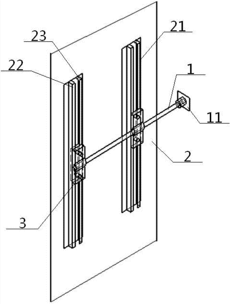
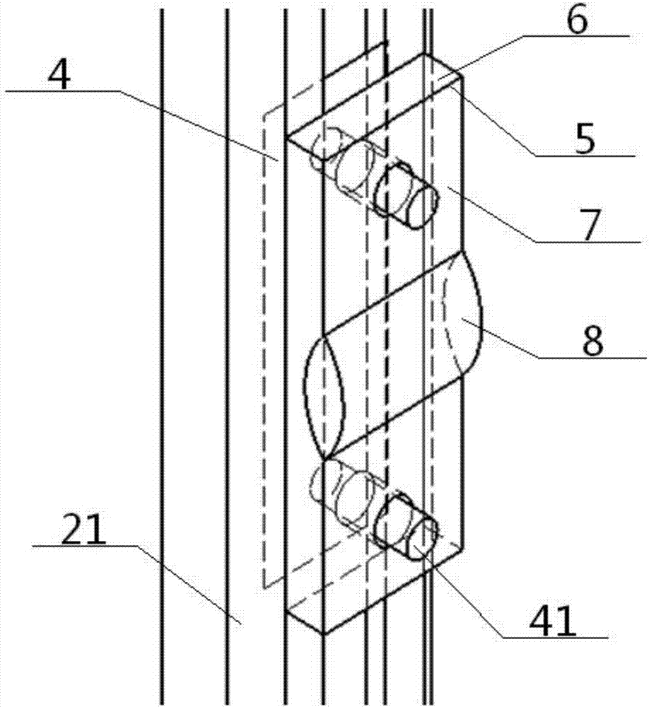
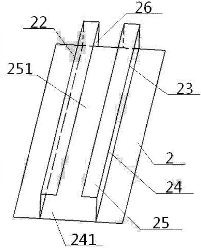
[0059] see Figure 1 to Figure 6 , an adjustable fender for a commercial vehicle, comprising a connecting rod 1, a fender 2 and an installation adjustment mechanism 3, one end of the connecting rod 1 is connected to a support seat 11, and the other end of the connecting rod 1 is connected to the installation adjustment mechanism The mechanisms 3 are connected, and the installation and adjustment mechanism 3 slides up and down along the fender 2; the fender 2 is fixedly connected with an installation card slot 21, and the installation card slot 21 includes a left card slot plate 22 that is left and right symmetrical and has the same structure , right draw-in groove plate 23, described left draw-in groove plate 22, right draw-in groove plate 23 all comprise vertical support plate 24, horizontal support plate 25, the bottom of vertical support plate 24 is vertically connected with fender 2, vertical support plate 24 The top of the top is vertically connected with the horizontal s...
Embodiment 2
[0062] Basic content is the same as embodiment 1, the difference is:
[0063] The clamping structure 5 includes a vibration-damping block 6 and a pressure plate 7. A vibration-damping perforation 61 is respectively provided at the upper and lower ends of the vibration-damping block 6, and a pressure perforation 71 is respectively provided at the upper and lower ends of the pressure plate 7. The upper and lower ends of the clamping plate 4 are respectively provided with a clamping bolt shaft 41, and the clamping bolt shaft 41 passes through the transverse branch gap 251, the vibration-damping perforation 61, and the pressure perforation 71 in sequence, and then is threadedly connected with the nut, and The damping block 6 and the pressing plate 7 clamp the other end of the connecting rod 1 together.
[0064] The connecting of the clamping plate 4 and the clamping structure 5 means that the clamping bolt shaft 41 passes through the transverse branch gap 251, the vibration-dampin...
Embodiment 3
[0066] Basic content is the same as embodiment 2, the difference is:
[0067] The damping block 6 includes an upper block 62, a concave body 63 and a lower block 64 from top to bottom, and the upper and lower ends of the concave body 63 are respectively connected with the upper block 62 and the lower block 64. , the middle part of the concave body 63 is provided with a sunken lower groove 82, and each of the upper block body 62 and the lower block body 64 is provided with a vibration-damping perforation 61; the pressure plate 7 includes an upper plate body from top to bottom 72, the convex body 73 and the lower plate body 74, the upper and lower ends of the convex body 73 are connected with the upper plate body 72 and the lower plate body 74 respectively, and the middle part of the convex body 73 is provided with a convex and connected with the lower plate body. The upper convex groove 81 corresponding to the groove 82, the upper convex groove 81 and the lower groove 82 surrou...
PUM
 Abstract
Description
Claims
Application Information
 - R&D
- Intellectual Property
- Life Sciences
- Materials
- Tech Scout
- Unparalleled Data Quality
- Higher Quality Content
- 60% Fewer Hallucinations
Browse by: Latest US Patents, China's latest patents, Technical Efficacy Thesaurus, Application Domain, Technology Topic, Popular Technical Reports.
© 2025 PatSnap. All rights reserved.Legal|Privacy policy|Modern Slavery Act Transparency Statement|Sitemap|About US| Contact US: help@patsnap.com


