Electric unmanned aerial vehicle pan-tilt

A machine gimbal, electric technology, applied in the field of unmanned aerial vehicles, can solve the problem of inability to adjust the camera angle, and achieve the effect of changing the pitch angle and improving the shooting effect.

Inactive Publication Date: 2017-09-08
芜湖元一航空科技有限公司
View PDF0 Cites 4 Cited by
  • Summary
  • Abstract
  • Description
  • Claims
  • Application Information

AI Technical Summary

Problems solved by technology

[0002] Nowadays, when it comes to drones, most people think of aerial photography of drones, and aerial photography will use cameras and other video equipment, and cameras and other video equipment are fixed through the drone platform, and the drone platform is used as a drone The important part of the camera is mainly divided into two types: fixed type and electric type. The fixed type is adjusted and then fixed, and then the angle of the camera cannot be adjusted. In this invention, an electric drone platform is provided.

Method used


Image

  • Electric unmanned aerial vehicle pan-tilt
  • Electric unmanned aerial vehicle pan-tilt
  • Electric unmanned aerial vehicle pan-tilt

Examples


specific Embodiment approach

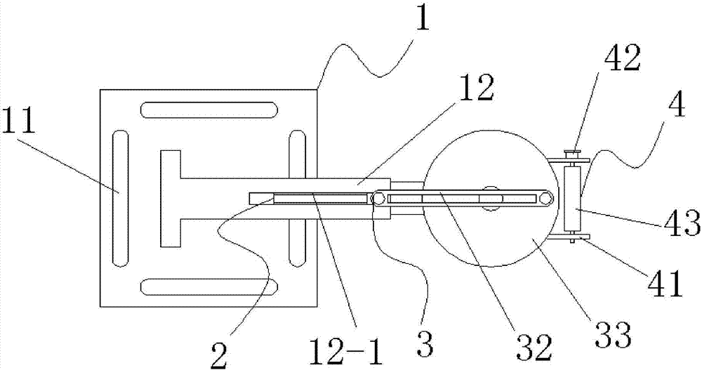
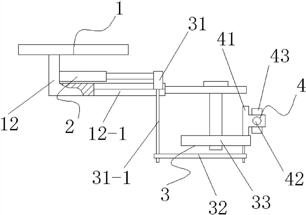
[0014] figure 1 , figure 2 and image 3 The specific embodiment of the present invention is shown: an electric UAV platform, including a fixed seat 1, a miniature electric push rod 2, a centering slider mechanism 3 and a camera fixing mechanism 4, and the miniature electric push rod 2 and the fixed seat 1 is fixedly connected, the centering slider mechanism 3 is fixedly connected to the miniature electric push rod 2, and the camera fixing mechanism 4 is fixedly connected to the centering slider mechanism 3.

[0015] In this embodiment, four fixing holes 11 are evenly distributed on the fixing seat 1, and an extension rod 12 is provided on the lower bottom surface, and the miniature electric push rod 2 is fixedly connected to the side wall of the extension rod 12, and the extension rod 12 is An escape slot 12-1 is provided, and the miniature electric push rod 2 drives the slide block 31 to perform linear motion of reciprocating sliding, and the escape slot 12-1 avoids the ex...

Embodiment 1

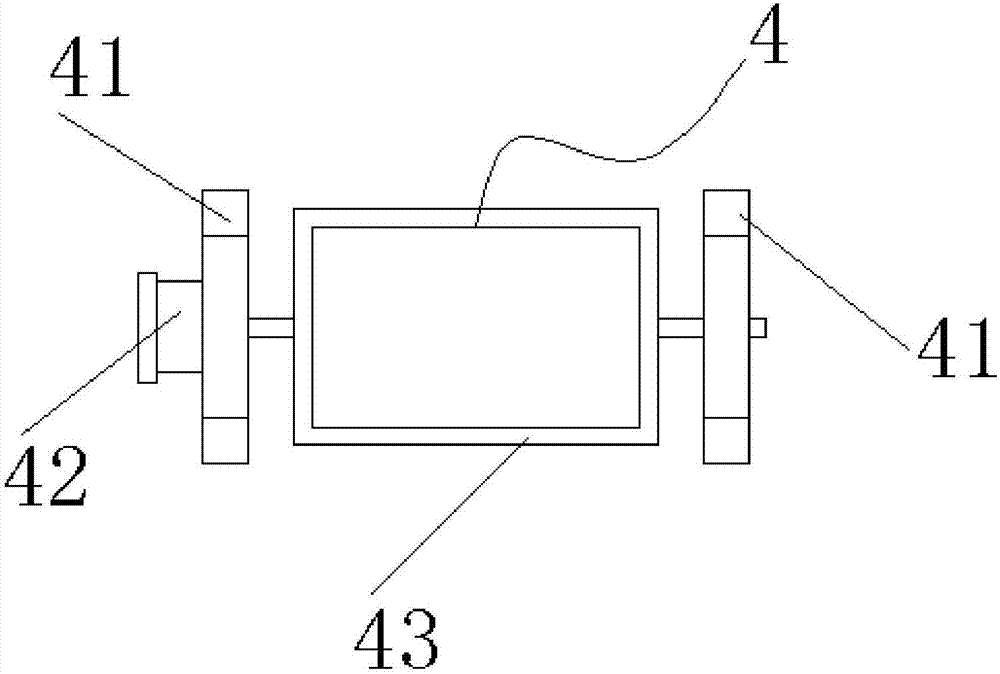
[0020] Based on the above, the structure of the present invention is an electric unmanned aerial vehicle platform, which is fastened on the unmanned aerial vehicle through the fixing hole 11 by screws, and the unmanned aerial vehicle is generally controlled by a remote controller. At this time, remote control the miniature electric push rod 2 to make it expand and contract, and the telescopic movement of the miniature electric push rod 2 drives the slider 31 to reciprocate on the extension rod 12 to make a linear motion, and the reciprocating sliding linear motion of the slider 31 is transformed by the connecting rod 32 For the circular movement of the turntable 33, the camera is fixed on the camera fixing mechanism 4, and the camera fixing mechanism 4 is fixedly installed on the turntable 33, and the circular movement of the turntable 33 drives the camera to perform 360-degree panoramic shooting, and the remote control micro-motor 42, the motor 42 rotates at a certain angle , ...


PUM


Abstract

The invention discloses an electric unmanned aerial vehicle platform, which relates to the technical field of unmanned aerial vehicles, and comprises a fixed seat, a miniature electric push rod, a centering slider mechanism and a camera fixing mechanism, and the miniature electric push rod is fixedly connected with the fixed seat , the centering slider mechanism is fixedly connected with the miniature electric push rod, and the camera fixing mechanism is fixedly connected with the centering slider mechanism. The electric drone platform can not only change the pitch angle of the camera, but also realize a 360-degree panorama Shooting can meet the required shooting requirements and achieve the best shooting effect.

Description

technical field [0001] The invention relates to the technical field of drones, in particular to an electric drone platform. Background technique [0002] Nowadays, when it comes to drones, most people think of aerial photography of drones, and aerial photography will use cameras and other video equipment, and cameras and other video equipment are fixed through the drone platform, and the drone platform is used as a drone The important part of the camera is mainly divided into two types: fixed type and electric type. The fixed type is adjusted and then fixed, and then the angle of the camera cannot be adjusted. In this invention, an electric drone platform is provided. . Contents of the invention [0003] The invention provides an electric unmanned aerial vehicle platform, which can change the pitch angle of the camera through remote control, and can realize 360-degree panoramic shooting. [0004] In order to achieve the above object, the present invention provides the fo...

Claims


Application Information

Patent Timeline
Patent Type & Authority Applications(China)
IPC IPC(8): B64D47/08B64C39/02
CPCB64D47/08B64C39/02
Inventor 王会恩臧楠王启源
Owner 芜湖元一航空科技有限公司
Why Eureka
Try Eureka